
English Manual.
Page 5
... a certified computer technician. Installation Precautions WARNING! ■ Electrostatic discharge (ESD) is turned off before installing or removing CPU, memory, expansion cards or other peripherals. Normally it comes out as a motherboard, CPU or memory. ■ Ensure that the DC power supply is the sudden and momentary electric current that your system can operate...
... a certified computer technician. Installation Precautions WARNING! ■ Electrostatic discharge (ESD) is turned off before installing or removing CPU, memory, expansion cards or other peripherals. Normally it comes out as a motherboard, CPU or memory. ■ Ensure that the DC power supply is the sudden and momentary electric current that your system can operate...
English Manual.
Page 6
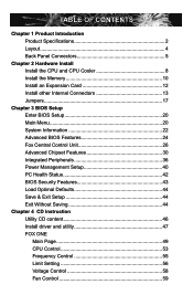
Table of Contents Chapter 1 Product Introduction Product Specifications 2 Layout 4 Back Panel Connectors 5 Chapter 2 Hardware Install Install the CPU and CPU Cooler 8 Install the Memory 10 Install an Expansion Card 12 Install other Internal Connectors 13 Jumpers 17 Chapter 3 BIOS Setup Enter BIOS Setup 20 Main Menu 20 System Information ...
Table of Contents Chapter 1 Product Introduction Product Specifications 2 Layout 4 Back Panel Connectors 5 Chapter 2 Hardware Install Install the CPU and CPU Cooler 8 Install the Memory 10 Install an Expansion Card 12 Install other Internal Connectors 13 Jumpers 17 Chapter 3 BIOS Setup Enter BIOS Setup 20 Main Menu 20 System Information ...

English Manual.
Page 7
... : http://www.foxconnchannel.com Support Support Website : http://www.foxconnchannel.com/support/online.aspx or http://www.foxconnsupport.com Worldwide E-mail Support : pcebg-cisg-support@foxconn.com CPU, Memory, VGA Compatibility Supporting Website : http://www.foxconnchannel.com/product/Motherboards/compatibility.aspx
... : http://www.foxconnchannel.com Support Support Website : http://www.foxconnchannel.com/support/online.aspx or http://www.foxconnsupport.com Worldwide E-mail Support : pcebg-cisg-support@foxconn.com CPU, Memory, VGA Compatibility Supporting Website : http://www.foxconnchannel.com/product/Motherboards/compatibility.aspx

English Manual.
Page 9
... 64 / SempronTM HyperTransport HT3.0 up to 5.2GT/s (depends on CPU) Chipset North Bridge: AMD 780G South Bridge: AMD SB700 Memory 4 x 240-pin DDR2 DIMM sockets Support up to 8GB of system memory Dual channel DDR2 1066/800/667/533/400MHz architecture Audio Realtek 8-channel audio chip High Definition Audio 2/4/5.1/7.1-channel Support for...
... 64 / SempronTM HyperTransport HT3.0 up to 5.2GT/s (depends on CPU) Chipset North Bridge: AMD 780G South Bridge: AMD SB700 Memory 4 x 240-pin DDR2 DIMM sockets Support up to 8GB of system memory Dual channel DDR2 1066/800/667/533/400MHz architecture Audio Realtek 8-channel audio chip High Definition Audio 2/4/5.1/7.1-channel Support for...

English Manual.
Page 14
This chapter includes the following information : ■ Install the CPU and CPU Cooler ■ Install the Memory ■ Install an Expansion Card ■ Install other Internal Connectors ■ Jumpers Please visit this chapter carefully. Please refer to ...the motherboard layout prior to any installation and read the contents in this website for more supporting information about CPU, Memory and VGA for your motherboard : http://www.foxconnchannel.com/product/Motherboards/compatibility.aspx This chapter introduces the hardware installation process, including the ...
This chapter includes the following information : ■ Install the CPU and CPU Cooler ■ Install the Memory ■ Install an Expansion Card ■ Install other Internal Connectors ■ Jumpers Please visit this chapter carefully. Please refer to ...the motherboard layout prior to any installation and read the contents in this website for more supporting information about CPU, Memory and VGA for your motherboard : http://www.foxconnchannel.com/product/Motherboards/compatibility.aspx This chapter introduces the hardware installation process, including the ...

English Manual.
Page 15
... the CPU specifications. Release the CPU socket lever. 2. Read the following guidelines before installing the CPU to your hardware specifications including the CPU, graphics card, memory, hard drive, etc. It is not recommended that the system bus frequency be inserted if oriented incorrectly. ■ Apply an even and thin layer of...
... the CPU specifications. Release the CPU socket lever. 2. Read the following guidelines before installing the CPU to your hardware specifications including the CPU, graphics card, memory, hard drive, etc. It is not recommended that the system bus frequency be inserted if oriented incorrectly. ■ Apply an even and thin layer of...
English Manual.
Page 17
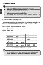
... capacity, brand, speed, and chips be installed in your system. DS/SS Single Channel - - Dual Channel - - A memory module can be used . ■ Always turn off the computer and unplug the power cord from the power outlet before you ... Single Channel DS/SS - - DS/SS Single Channel - Dual Channel Memory Configuration This motherboard provides four DDR2 memory sockets and supports Dual Channel Technology. Read the following guidelines before installing the memory to insert the memory, switch the direction. It is installed, the BIOS will automatically check the...
... capacity, brand, speed, and chips be installed in your system. DS/SS Single Channel - - Dual Channel - - A memory module can be used . ■ Always turn off the computer and unplug the power cord from the power outlet before you ... Single Channel DS/SS - - DS/SS Single Channel - Dual Channel Memory Configuration This motherboard provides four DDR2 memory sockets and supports Dual Channel Technology. Read the following guidelines before installing the memory to insert the memory, switch the direction. It is installed, the BIOS will automatically check the...
English Manual.
Page 18
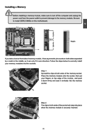
... a look at front side of the module, and push it down firmly and seat it vertically into the memory socket. Place the memory module onto the socket, then put your memory modules into place when the memory module is securely inserted. 11 Step 2: The clips at both ends of the socket will snap into..., make sure to turn off the computer and unplug the power cord from the power outlet to prevent damage to the memory module. Step 1: Spread the clips at both sides separated by a notch in the middle, so it has asymmetric pin counts on this motherboard. CAUTION 2 112-...
... a look at front side of the module, and push it down firmly and seat it vertically into the memory socket. Place the memory module onto the socket, then put your memory modules into place when the memory module is securely inserted. 11 Step 2: The clips at both ends of the socket will snap into..., make sure to turn off the computer and unplug the power cord from the power outlet to prevent damage to the memory module. Step 1: Spread the clips at both sides separated by a notch in the middle, so it has asymmetric pin counts on this motherboard. CAUTION 2 112-...

English Manual.
Page 27
... to maintain optimal system performance. There are boot up settings. ► Fox Central Control Unit Some special proprietary features (such as BIOS ID, CPU Name, memory size plus system date, time and Floppy drive. appears at the bottom of setup functions together with two exit choices. Each item in the BIOS...
... to maintain optimal system performance. There are boot up settings. ► Fox Central Control Unit Some special proprietary features (such as BIOS ID, CPU Name, memory size plus system date, time and Floppy drive. appears at the bottom of setup functions together with two exit choices. Each item in the BIOS...
English Manual.
Page 28
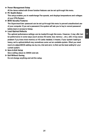
..., the system will ask you to key in some ways (such as less I /O cards installed. However, it may cause problem if you have more memory or I /O cards, less memory ...etc.), still, it may sometimes come out an unstable system. 3 ► Power Management Setup All the items related with Green function features can...
..., the system will ask you to key in some ways (such as less I /O cards installed. However, it may cause problem if you have more memory or I /O cards, less memory ...etc.), still, it may sometimes come out an unstable system. 3 ► Power Management Setup All the items related with Green function features can...

English Manual.
Page 30
... Model Name Model name of this information and discuss with the field service people if a BIOS upgrade is depending on how many memory modules were installed in your system before powering on. ► MAC Address This item shows the onboard LAN MAC address. SATA 5...5 - - - - SATA 3 SATA 3 SATA 3 - - The size is needed. ► CPU Name It displays the current CPU name. ► System Memory Size This item displays the current memory size. SATA 6 IDE1 Secondary IDE Master SATA 5 IDE0 - Third IDE Master SATA 1 SATA 1 SATA 1 SATA 1 - Fourth IDE Slave SATA 4 SATA 4 ...
... Model Name Model name of this information and discuss with the field service people if a BIOS upgrade is depending on how many memory modules were installed in your system before powering on. ► MAC Address This item shows the onboard LAN MAC address. SATA 5...5 - - - - SATA 3 SATA 3 SATA 3 - - The size is needed. ► CPU Name It displays the current CPU name. ► System Memory Size This item displays the current memory size. SATA 6 IDE1 Secondary IDE Master SATA 5 IDE0 - Third IDE Master SATA 1 SATA 1 SATA 1 SATA 1 - Fourth IDE Slave SATA 4 SATA 4 ...

English Manual.
Page 34
System Status Normal No Memory No Display Post Error Message No CPU Fan Power LED Status Always On Continue blinking On (1sec.), Off (1sec.) Continue blinking On (2sec.), Off (2sec.) ... during Power On System Test (POST). You can always leave this state enabled. Continue blinking On (1/2sec.), Off (1/2sec.) Stop Blinking Condition Always On Reboot & Memory OK Reboot & Display OK Enter Setup or Skip Reboot & Fan OK ► Smart Boot Menu When PC starts, it displays POST state by different long...
System Status Normal No Memory No Display Post Error Message No CPU Fan Power LED Status Always On Continue blinking On (1sec.), Off (1sec.) Continue blinking On (2sec.), Off (2sec.) ... during Power On System Test (POST). You can always leave this state enabled. Continue blinking On (1/2sec.), Off (1/2sec.) Stop Blinking Condition Always On Reboot & Memory OK Reboot & Display OK Enter Setup or Skip Reboot & Fan OK ► Smart Boot Menu When PC starts, it displays POST state by different long...

English Manual.
Page 35
... option will be displayed only if your CPU. Voltage Options CMOS Setup Utility - Voltage Options CPU Voltage Control [Disabled] Help Item Memory Voltage Control NB Voltage Control [Disabled] [Disabled] Options HT/SB Voltage Control [Disabled] Disabled +25mV +50mV +75mV +100mV +125mV...30mV. Copyright (C) 1985-2006, American Megatrends, Inc. The voltage can be incremented from +25mV to +775mV. ► Memory Voltage Control This option is activated, you can be incremented from +30mV to +360mV. ► HT/SB Voltage Control ...
... option will be displayed only if your CPU. Voltage Options CMOS Setup Utility - Voltage Options CPU Voltage Control [Disabled] Help Item Memory Voltage Control NB Voltage Control [Disabled] [Disabled] Options HT/SB Voltage Control [Disabled] Disabled +25mV +50mV +75mV +100mV +125mV...30mV. Copyright (C) 1985-2006, American Megatrends, Inc. The voltage can be incremented from +25mV to +775mV. ► Memory Voltage Control This option is activated, you can be incremented from +30mV to +360mV. ► HT/SB Voltage Control ...

English Manual.
Page 36
...link using multipliers ranging 1x to 13x. The HyperTransport link width and frequency are coherent HT links as they do not have memory cache. 3 CPU Configuration CMOS Setup Utility - This item is slowing down the CPU frequency and voltage when system is determined... CPU Configuration Help Item Module Version : 13.23 AGESA Version : 3.1.5.0 Enable/disable the Physical Count : 1 generation of memory, and the HT links between processors are initialized between the adjacent coherent and/or noncoherent HyperTransport technology devices during the reset sequence.
...link using multipliers ranging 1x to 13x. The HyperTransport link width and frequency are coherent HT links as they do not have memory cache. 3 CPU Configuration CMOS Setup Utility - This item is slowing down the CPU frequency and voltage when system is determined... CPU Configuration Help Item Module Version : 13.23 AGESA Version : 3.1.5.0 Enable/disable the Physical Count : 1 generation of memory, and the HT links between processors are initialized between the adjacent coherent and/or noncoherent HyperTransport technology devices during the reset sequence.

English Manual.
Page 37
...Features CMOS Setup Utility - Copyright (C) 1985-2006, American Megatrends, Inc. Advanced Chipset Features Northbridge Chipset Configuration Help Item ► Memory Configuration [Press Enter] ► DRAM Timing Configuration [Press Enter] CAS Latency :4 CLK RAS/CAS Delay :4 CLK Row Precharge... signals. ► Row Cycle This item displays the minimum timing interval between issuing of available resources for use as video memory to the same bank. The CAS Latency is the number of clock cycles that elapse from the module. ► RAS...
...Features CMOS Setup Utility - Copyright (C) 1985-2006, American Megatrends, Inc. Advanced Chipset Features Northbridge Chipset Configuration Help Item ► Memory Configuration [Press Enter] ► DRAM Timing Configuration [Press Enter] CAS Latency :4 CLK RAS/CAS Delay :4 CLK Row Precharge... signals. ► Row Cycle This item displays the minimum timing interval between issuing of available resources for use as video memory to the same bank. The CAS Latency is the number of clock cycles that elapse from the module. ► RAS...
English Manual.
Page 38
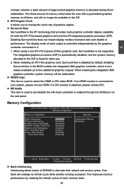
... rear panel. Copyright (C) 1985-2006, American Megatrends, Inc. The display mode of each memory bank. 31 The integrated graphics processor (IGP) is automatically disabled, and the system memory allocated to the IGP is controlled independently by the graphics controller connected to change the clock...display capability for other use. 2. When installing an ATI PCIe graphics card, SurroundView is allocated during driver initialization. This improves memory performance by masking the refresh cycles of each output is freed for both the ATI PCIe-based graphics card and the ATI integrated...
... rear panel. Copyright (C) 1985-2006, American Megatrends, Inc. The display mode of each memory bank. 31 The integrated graphics processor (IGP) is automatically disabled, and the system memory allocated to the IGP is controlled independently by the graphics controller connected to change the clock...display capability for other use. 2. When installing an ATI PCIe graphics card, SurroundView is allocated during driver initialization. This improves memory performance by masking the refresh cycles of each output is freed for both the ATI PCIe-based graphics card and the ATI integrated...

English Manual.
Page 39
... 0 DIMM3 Channel 1 DIMM4 512MB 1GB 512MB Channel 0 DIMM1 Channel 1 DIMM2 Channel 0 DIMM3 Channel 1 DIMM4 1GB 1GB 3 Matched in both Channel 0 and Channel 1 memory channels ► Enable Clock to All DIMMs This setting is to associate addresses with physical addresses larger than 32 bits. Many systems cause that high... turn off clock on the empty DIMM slots and to reduce EMI (Electro-Magnetic Interference). ► MemClk Tristate C3/ALTVID Enables the DDR memory clocks to be used , but by convention the PC platform puts them at the top of both DIMM channels are equal. Of course,...
... 0 DIMM3 Channel 1 DIMM4 512MB 1GB 512MB Channel 0 DIMM1 Channel 1 DIMM2 Channel 0 DIMM3 Channel 1 DIMM4 1GB 1GB 3 Matched in both Channel 0 and Channel 1 memory channels ► Enable Clock to All DIMMs This setting is to associate addresses with physical addresses larger than 32 bits. Many systems cause that high... turn off clock on the empty DIMM slots and to reduce EMI (Electro-Magnetic Interference). ► MemClk Tristate C3/ALTVID Enables the DDR memory clocks to be used , but by convention the PC platform puts them at the top of both DIMM channels are equal. Of course,...

English Manual.
Page 40
...-bit DRAM data width) and unganged (64-bit DRAM data width) DRAM modes : Ganged channels (DDR2) : ■ DCT channels A and B can be set to access memory. A DIMM or a group of the DRAMs associated with the channel are pending for the chip select(s). 33 The DRAM channel is enabled, if all chip...
...-bit DRAM data width) and unganged (64-bit DRAM data width) DRAM modes : Ganged channels (DDR2) : ■ DCT channels A and B can be set to access memory. A DIMM or a group of the DRAMs associated with the channel are pending for the chip select(s). 33 The DRAM channel is enabled, if all chip...

English Manual.
Page 41
... listed in clock cycles) between the CAS# and RAS# strobe signals. 34 DRAM Timing Configuration DRAM Timing Configuration Help Item Memory Speed Mode [Auto] DRAM Timing Mode [Auto] Options Auto Limit Manual 3 Move Enter:Select +/-/:Value F10:Save ESC:Exit... F1:General Help F9:Optimized Defaults ► Memory Speed Mode This item is selected. Otherwise, SPD value is used to [Limit] or [Manual]. Settings are enabled in unganged mode...
... listed in clock cycles) between the CAS# and RAS# strobe signals. 34 DRAM Timing Configuration DRAM Timing Configuration Help Item Memory Speed Mode [Auto] DRAM Timing Mode [Auto] Options Auto Limit Manual 3 Move Enter:Select +/-/:Value F10:Save ESC:Exit... F1:General Help F9:Optimized Defaults ► Memory Speed Mode This item is selected. Otherwise, SPD value is used to [Limit] or [Manual]. Settings are enabled in unganged mode...

English Manual.
Page 42
.../Auto-Refresh Command Period) This item allows you to select a delay time (in clock cycles) between sending the last data from a write operation to the memory and issuing a read to a different chip select. ► tRFC0, 1, 2, 3 (Auto-Refresh-to-Active/Auto-Refresh Command Period) Refresh to Refresh or Refresh to Write Timing...
.../Auto-Refresh Command Period) This item allows you to select a delay time (in clock cycles) between sending the last data from a write operation to the memory and issuing a read to a different chip select. ► tRFC0, 1, 2, 3 (Auto-Refresh-to-Active/Auto-Refresh Command Period) Refresh to Refresh or Refresh to Write Timing...
