
English Manual.
Page 6
...10 Install an Expansion Card 12 Install other Internal Connectors 13 Jumpers 16 Onboard Button 19 Chapter 3 BIOS Setup Enter BIOS Setup 21 Main Menu 21 System Information 23 Advanced BIOS Features 25 Fox Central Control Unit 27 Advanced Chipset Features 33 Integrated Peripherals 38 Power Management Setup 42... PC Health Status 44 BIOS Security Features 45 Load Optimal Defaults 46 Save Changes and Exit 46 Discard Changes and Exit 46 Chapter 4 CD Instruction ...
...10 Install an Expansion Card 12 Install other Internal Connectors 13 Jumpers 16 Onboard Button 19 Chapter 3 BIOS Setup Enter BIOS Setup 21 Main Menu 21 System Information 23 Advanced BIOS Features 25 Fox Central Control Unit 27 Advanced Chipset Features 33 Integrated Peripherals 38 Power Management Setup 42... PC Health Status 44 BIOS Security Features 45 Load Optimal Defaults 46 Save Changes and Exit 46 Discard Changes and Exit 46 Chapter 4 CD Instruction ...

English Manual.
Page 7
... 69 FOX LOGO 70 FOX DMI 71 Chapter 5 RAID Configuration RAID Configuration Introduction 74 FastBuild Driver 76 Create a RAID Driver Diskette 78 RAID Enable in BIOS 80 Select a RAID Array for Use 80 Install a New Windows XP 95 Setting Up a Non-Bootable RAID Array 99 Technical Support : Website : http://www.foxconnchannel...
... 69 FOX LOGO 70 FOX DMI 71 Chapter 5 RAID Configuration RAID Configuration Introduction 74 FastBuild Driver 76 Create a RAID Driver Diskette 78 RAID Enable in BIOS 80 Select a RAID Array for Use 80 Install a New Windows XP 95 Setting Up a Non-Bootable RAID Array 99 Technical Support : Website : http://www.foxconnchannel...

English Manual.
Page 17
... Memory) DS/SS DS/SS ! Read the following guidelines before installing the memory to achieve optimum performance. Single Channel DS/SS - It is installed, the BIOS will automatically check the memory in only one direction. CAUTION 10 A memory module can be used and please select dual channel first to prevent hardware...
... Memory) DS/SS DS/SS ! Read the following guidelines before installing the memory to achieve optimum performance. Single Channel DS/SS - It is installed, the BIOS will automatically check the memory in only one direction. CAUTION 10 A memory module can be used and please select dual channel first to prevent hardware...

English Manual.
Page 19
... install your card. Locate an expansion slot that supports your expansion card in the expansion slot. 1. Secure the card's metal bracket to make any required BIOS changes for your expansion card. ■ Always turn off the computer and unplug the power cord from the chassis back panel. 2. Turn on your operating...the PCI Express x16 slot to prevent hardware damage. ■ The PCI-E2_16X slot will work at PCI Express x8 mode. If necessary, go to BIOS Setup to the chassis back panel with the slot, and press down on the card are completely inserted into the PCI Express x16 slot. Align...
... install your card. Locate an expansion slot that supports your expansion card in the expansion slot. 1. Secure the card's metal bracket to make any required BIOS changes for your expansion card. ■ Always turn off the computer and unplug the power cord from the chassis back panel. 2. Turn on your operating...the PCI Express x16 slot to prevent hardware damage. ■ The PCI-E2_16X slot will work at PCI Express x8 mode. If necessary, go to BIOS Setup to the chassis back panel with the slot, and press down on the card are completely inserted into the PCI Express x16 slot. Align...

English Manual.
Page 24
.... +5V 1 EMPTY 2 SPDIF_OUT 3 GND 4 SPDIF_OUT 1 GND POWER SENSE CONTROL CPU_FAN / SYS_FAN / NB_FAN Speaker Connector : SPEAKER The speaker connector is used to connect speaker of the BIOS Setup. The fan speed can be controlled and monitored in "PC Health Status" section of the chassis.
.... +5V 1 EMPTY 2 SPDIF_OUT 3 GND 4 SPDIF_OUT 1 GND POWER SENSE CONTROL CPU_FAN / SYS_FAN / NB_FAN Speaker Connector : SPEAKER The speaker connector is used to connect speaker of the BIOS Setup. The fan speed can be controlled and monitored in "PC Health Status" section of the chassis.

English Manual.
Page 25
... were mistakenly modified. The shorting can also be identified by changing the jumper settings. Go to BIOS Setup to configure new system as BIOS data, date, time information, hardware password...etc.). "Closed" means placing a jumper cap on the two pins to temporarily short them . Jumper 1 Diagram 1 1 Definition 1-2 2-3 Description Set ...
... were mistakenly modified. The shorting can also be identified by changing the jumper settings. Go to BIOS Setup to configure new system as BIOS data, date, time information, hardware password...etc.). "Closed" means placing a jumper cap on the two pins to temporarily short them . Jumper 1 Diagram 1 1 Definition 1-2 2-3 Description Set ...
English Manual.
Page 27
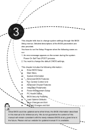
...the following cases occur: 1. You have to run the Setup Program when the following information : ■ Enter BIOS Setup ■ Main Menu ■ System Information ■ Advanced BIOS Features ■ Fox Central Control Unit ■ Advanced Chipset Features ■ Integrated Peripherals ■ Power Management Setup...Features ■ Load Optimal Defaults ■ Save Changes and Exit ■ Discard Changes and Exit Since BIOS could be updated some other times, the BIOS information described in the future. An error message appears on the screen during the system Power On Self Test...
...the following cases occur: 1. You have to run the Setup Program when the following information : ■ Enter BIOS Setup ■ Main Menu ■ System Information ■ Advanced BIOS Features ■ Fox Central Control Unit ■ Advanced Chipset Features ■ Integrated Peripherals ■ Power Management Setup...Features ■ Load Optimal Defaults ■ Save Changes and Exit ■ Discard Changes and Exit Since BIOS could be updated some other times, the BIOS information described in the future. An error message appears on the screen during the system Power On Self Test...

English Manual.
Page 28
...Display System Information... Copyright (C) 1985-2006, American Megatrends, Inc. ► System Information ► PC Health Status ► Advanced BIOS Features ► BIOS Security Features ► Fox Central Control Unit Load Optimal Defaults ► Advanced Chipset Features Save Changes and Exit ► Integrated ...:Optimized Defaults Configure Time and Date. They all can be viewed or set up through this menu. ► Advanced BIOS Features The advanced system features can be set up through this menu. ► Advanced Chipset Features The values for any...
...Display System Information... Copyright (C) 1985-2006, American Megatrends, Inc. ► System Information ► PC Health Status ► Advanced BIOS Features ► BIOS Security Features ► Fox Central Control Unit Load Optimal Defaults ► Advanced Chipset Features Save Changes and Exit ► Integrated ...:Optimized Defaults Configure Time and Date. They all can be viewed or set up through this menu. ► Advanced BIOS Features The advanced system features can be set up through this menu. ► Advanced Chipset Features The values for any...

English Manual.
Page 29
... you to CMOS and exit. ► Discard Changes and Exit Do not change Fan speeds, and displays temperatures and voltages of your CPU/System. ► BIOS Security Features The Supervisor/User password can be set to optimal default may cause problem if you need now is heavy, set up through this... Changes and Exit Save setting values to key in some ways (such as less I /O cards installed. It means, if your system loading is to adjust BIOS setting one by one, trial and error, to find out the best setting for your computer.
... you to CMOS and exit. ► Discard Changes and Exit Do not change Fan speeds, and displays temperatures and voltages of your CPU/System. ► BIOS Security Features The Supervisor/User password can be set to optimal default may cause problem if you need now is heavy, set up through this... Changes and Exit Save setting values to key in some ways (such as less I /O cards installed. It means, if your system loading is to adjust BIOS setting one by one, trial and error, to find out the best setting for your computer.

English Manual.
Page 30
...[Not Detected] Floppy A Halt On Keyboard Mouse Floppy [1.44 MB 31/2"] [All Errors, But ...] [Disabled] [Disabled] [Disabled] Model Name BIOS ID : A7DA-S/A7DA : 81BF1P01 Move Enter:Select +/-/:Value F10:Save ESC:Exit F1:General Help F9:Optimized Defaults ► Date (mm:dd:yy) format. SATA3#... the value. Use [+] or [-] to 12. The three fields of the setting are : : respectively. ► IDE Master / Slave While entering setup, BIOS automatically detects the presence of IDE devices. ► SATA1# / SATA2# / SATA3# / SATA4# / SATA5# / E-SATA# When OnChip SATA Type is ...
...[Not Detected] Floppy A Halt On Keyboard Mouse Floppy [1.44 MB 31/2"] [All Errors, But ...] [Disabled] [Disabled] [Disabled] Model Name BIOS ID : A7DA-S/A7DA : 81BF1P01 Move Enter:Select +/-/:Value F10:Save ESC:Exit F1:General Help F9:Optimized Defaults ► Date (mm:dd:yy) format. SATA3#... the value. Use [+] or [-] to 12. The three fields of the setting are : : respectively. ► IDE Master / Slave While entering setup, BIOS automatically detects the presence of IDE devices. ► SATA1# / SATA2# / SATA3# / SATA4# / SATA5# / E-SATA# When OnChip SATA Type is ...

English Manual.
Page 31
... Name It displays the current CPU name. ► Memory This item displays the current memory size. User can check this product. ► BIOS ID / BIOS Version It displays the current BIOS ID/version. 3 It can be enabled/disabled in the next three settings. ► Keyboard The system boot will not stop for a keyboard... stop for a mouse error if you enabled this item. ► Model Name Model name of this information and discuss with the field service people if a BIOS upgrade is depending on how many memory modules were installed in system halt.
... Name It displays the current CPU name. ► Memory This item displays the current memory size. User can check this product. ► BIOS ID / BIOS Version It displays the current BIOS ID/version. 3 It can be enabled/disabled in the next three settings. ► Keyboard The system boot will not stop for a keyboard... stop for a mouse error if you enabled this item. ► Model Name Model name of this information and discuss with the field service people if a BIOS upgrade is depending on how many memory modules were installed in system halt.

English Manual.
Page 32
... PCI device can retain control of PCI cycle for MPS 1.4, you are 32, 64, 96, 128, 160, 192, 224, 248. Advanced BIOS Features IDE Detect Time Out MPS Revision PCI Latency Timer Quiet Boot Quick Boot Bootup Num-Lock Floppy Drive Seek ► Boot Device Priority ►... the effective PCI bandwidth while higher values means every PCI device will use of the MPS that doesn't come with two or more processors. Advanced BIOS Features CMOS Setup Utility - MPS 1.1 was the original specification. Low values for a longer time. Normally, a default value of other devices on a ...
... PCI device can retain control of PCI cycle for MPS 1.4, you are 32, 64, 96, 128, 160, 192, 224, 248. Advanced BIOS Features IDE Detect Time Out MPS Revision PCI Latency Timer Quiet Boot Quick Boot Bootup Num-Lock Floppy Drive Seek ► Boot Device Priority ►... the effective PCI bandwidth while higher values means every PCI device will use of the MPS that doesn't come with two or more processors. Advanced BIOS Features CMOS Setup Utility - MPS 1.1 was the original specification. Low values for a longer time. Normally, a default value of other devices on a ...
English Manual.
Page 33
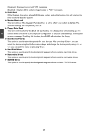
...the normal POST messages. [Enabled] : Displays OEM customer logo instead of POST messages. ► Quick Boot While Enabled, this option allows BIOS to skip certain tests while booting, this will shorten the time needed to specify the boot priority sequence from available removable drives. ►...device priority using or ; The available settings are: On (default) and Off. ► Floppy Drive Seek This item controls whether the BIOS will not detect the floppy. ► Boot Device Priority This option is used to improper configuration or physical unavailability), it cannot detect ...
...the normal POST messages. [Enabled] : Displays OEM customer logo instead of POST messages. ► Quick Boot While Enabled, this option allows BIOS to skip certain tests while booting, this will shorten the time needed to specify the boot priority sequence from available removable drives. ►...device priority using or ; The available settings are: On (default) and Off. ► Floppy Drive Seek This item controls whether the BIOS will not detect the floppy. ► Boot Device Priority This option is used to improper configuration or physical unavailability), it cannot detect ...

English Manual.
Page 34
...detect PCI slot. CIH. ► Auto Detect PCI Clock This option is a BIOS write-protection mechanism provided. Copyright (C) 1985-2006, American Megatrends, Inc. Super BIOS Protect function protects your BIOS from virus attack, there is used to its submenu. 27 3 Fox Central ...Control Unit CMOS Setup Utility - Fox Central Control Unit Super BIOS Protect Auto Detect PCI Clock ► Smart BIOS ► Fox Intelligent Stepping ► Voltage Options ► CPU Configuration [Disabled] Help Item [Enabled] [Press Enter...
...detect PCI slot. CIH. ► Auto Detect PCI Clock This option is a BIOS write-protection mechanism provided. Copyright (C) 1985-2006, American Megatrends, Inc. Super BIOS Protect function protects your BIOS from virus attack, there is used to its submenu. 27 3 Fox Central ...Control Unit CMOS Setup Utility - Fox Central Control Unit Super BIOS Protect Auto Detect PCI Clock ► Smart BIOS ► Fox Intelligent Stepping ► Voltage Options ► CPU Configuration [Disabled] Help Item [Enabled] [Press Enter...
English Manual.
Page 35
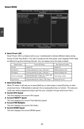
You can always leave this state enabled. This also prevents user without password trying to get into your motherboard to enter smart boot menu. Smart BIOS Smart Power LED [Enabled] Help Item Smart Boot Menu Current CPU Speed [Enabled] : 2600MHz Options Current FSB/HTT Speed : 1000MHz Current FSB Multiplier : 12.5x... key to enter setup or press [Esc] key to indicate different states during Power On Self Test (POST). Copyright (C) 1985-2006, American Megatrends, Inc. Smart BIOS CMOS Setup Utility - On, 1/3sec. The LED is selected, then pressing [Esc] has no function.
You can always leave this state enabled. This also prevents user without password trying to get into your motherboard to enter smart boot menu. Smart BIOS Smart Power LED [Enabled] Help Item Smart Boot Menu Current CPU Speed [Enabled] : 2600MHz Options Current FSB/HTT Speed : 1000MHz Current FSB Multiplier : 12.5x... key to enter setup or press [Esc] key to indicate different states during Power On Self Test (POST). Copyright (C) 1985-2006, American Megatrends, Inc. Smart BIOS CMOS Setup Utility - On, 1/3sec. The LED is selected, then pressing [Esc] has no function.

English Manual.
Page 37
This option will be valid if your CPU ratio is unlocked and will be noticed to achieve the function, including AMD OverDrive tool and compatible BIOS. Other (non processor-processor) HT links are initialized between processors are :[Disabled], [Auto], [All Cores], [Per Core]. 30 But if overclocking is determined by the ...
This option will be valid if your CPU ratio is unlocked and will be noticed to achieve the function, including AMD OverDrive tool and compatible BIOS. Other (non processor-processor) HT links are initialized between processors are :[Disabled], [Auto], [All Cores], [Per Core]. 30 But if overclocking is determined by the ...
English Manual.
Page 41
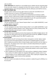
... system memory for both the ATI PCIe-based graphics card and the ATI integrated graphics processor (IGP). Enabling SurroundView in the BIOS enables the integrated UMA graphics controller, which in turn makes available up to select the priority of each output is set to...with a guaranteed graphics memory at all times, and will appear only when "Internal Graphics Mode" is controlled independently by default. 3 within the BIOS. [UMA+SIDEPORT]-The SidePort is disabled by the graphics controller connected to it used to the Unified Memory Architecture (UMA) concept, wherein a...
... system memory for both the ATI PCIe-based graphics card and the ATI integrated graphics processor (IGP). Enabling SurroundView in the BIOS enables the integrated UMA graphics controller, which in turn makes available up to select the priority of each output is set to...with a guaranteed graphics memory at all times, and will appear only when "Internal Graphics Mode" is controlled independently by default. 3 within the BIOS. [UMA+SIDEPORT]-The SidePort is disabled by the graphics controller connected to it used to the Unified Memory Architecture (UMA) concept, wherein a...

English Manual.
Page 42
... hole [Channel] 3 Move Enter:Select +/-/:Value F10:Save ESC:Exit F1:General Help F9:Optimized Defaults ► Memory Hole Remapping This item is enabled, the BIOS can deal with those storage cells. Memory Configuration CMOS Setup Utility - Copyright (C) 1985-2006, American Megatrends, Inc. PCI doesn't actually care much RAM into the...
... hole [Channel] 3 Move Enter:Select +/-/:Value F10:Save ESC:Exit F1:General Help F9:Optimized Defaults ► Memory Hole Remapping This item is enabled, the BIOS can deal with those storage cells. Memory Configuration CMOS Setup Utility - Copyright (C) 1985-2006, American Megatrends, Inc. PCI doesn't actually care much RAM into the...

English Manual.
Page 43
...AM2 CPU) Settings are two CKE pins per DRAM channel. 3 Burst lengths supported When both DCTs (DRAM controller) are enabled in unganged mode, BIOS must initialize the frequency of each DCT in order. ► Power Down Enable When power down mode is enabled, if all chip selects associated ... +/-/:Value F10:Save ESC:Exit F1:General Help F9:Optimized Defaults ► DRAM Timing Mode When both DCTs are enabled in unganged mode, BIOS must initialize the frequency of memory clocks it takes a DRAM to any of DIMMs enters power down mode by asserting the corresponding clock enable ...
...AM2 CPU) Settings are two CKE pins per DRAM channel. 3 Burst lengths supported When both DCTs (DRAM controller) are enabled in unganged mode, BIOS must initialize the frequency of each DCT in order. ► Power Down Enable When power down mode is enabled, if all chip selects associated ... +/-/:Value F10:Save ESC:Exit F1:General Help F9:Optimized Defaults ► DRAM Timing Mode When both DCTs are enabled in unganged mode, BIOS must initialize the frequency of memory clocks it takes a DRAM to any of DIMMs enters power down mode by asserting the corresponding clock enable ...

English Manual.
Page 48
... port 2. SuperIO Configuration SuperIO Configuration Help Item OnBoard Floppy Controller Serial Port1 Address Serial Port2 Address Serial Port2 Mode Serial Port2 Duplex Mode [Enabled] Allows BIOS to Enable [3F8/IRQ4] or disable floppy [2F8/IRQ3] controller. [IrDA] [Half Duplex] Move Enter:Select +/-/:Value F10:Save ESC:Exit F1:General Help F9...
... port 2. SuperIO Configuration SuperIO Configuration Help Item OnBoard Floppy Controller Serial Port1 Address Serial Port2 Address Serial Port2 Mode Serial Port2 Duplex Mode [Enabled] Allows BIOS to Enable [3F8/IRQ4] or disable floppy [2F8/IRQ3] controller. [IrDA] [Half Duplex] Move Enter:Select +/-/:Value F10:Save ESC:Exit F1:General Help F9...


