
English Manual.
Page 6
...10 Install an Expansion Card 12 Install other Internal Connectors 13 Jumpers 16 Onboard Button 19 Chapter 3 BIOS Setup Enter BIOS Setup 21 Main Menu 21 System Information 23 Advanced BIOS Features 25 Fox Central Control Unit 27 Advanced Chipset Features 33 Integrated Peripherals 38 Power Management Setup 42... PC Health Status 44 BIOS Security Features 45 Load Optimal Defaults 46 Save Changes and Exit 46 Discard Changes and Exit 46 Chapter 4 CD Instruction ...
...10 Install an Expansion Card 12 Install other Internal Connectors 13 Jumpers 16 Onboard Button 19 Chapter 3 BIOS Setup Enter BIOS Setup 21 Main Menu 21 System Information 23 Advanced BIOS Features 25 Fox Central Control Unit 27 Advanced Chipset Features 33 Integrated Peripherals 38 Power Management Setup 42... PC Health Status 44 BIOS Security Features 45 Load Optimal Defaults 46 Save Changes and Exit 46 Discard Changes and Exit 46 Chapter 4 CD Instruction ...

English Manual.
Page 7
... 69 FOX LOGO 70 FOX DMI 71 Chapter 5 RAID Configuration RAID Configuration Introduction 74 FastBuild Driver 76 Create a RAID Driver Diskette 78 RAID Enable in BIOS 80 Select a RAID Array for Use 80 Install a New Windows XP 95 Setting Up a Non-Bootable RAID Array 99 Technical Support : Website : http://www.foxconnchannel...
... 69 FOX LOGO 70 FOX DMI 71 Chapter 5 RAID Configuration RAID Configuration Introduction 74 FastBuild Driver 76 Create a RAID Driver Diskette 78 RAID Enable in BIOS 80 Select a RAID Array for Use 80 Install a New Windows XP 95 Setting Up a Non-Bootable RAID Array 99 Technical Support : Website : http://www.foxconnchannel...

English Manual.
Page 17
.../SS Dual Channel DS/SS DS/SS DS/SS (DS : Dual Side, SS : Single Side, - : No Memory) DS/SS DS/SS ! It is installed, the BIOS will automatically check the memory in only one direction. Single Channel DS/SS - CAUTION 10 DS/SS Dual Channel DS/SS DS/SS - - If you...
.../SS Dual Channel DS/SS DS/SS DS/SS (DS : Dual Side, SS : Single Side, - : No Memory) DS/SS DS/SS ! It is installed, the BIOS will automatically check the memory in only one direction. Single Channel DS/SS - CAUTION 10 DS/SS Dual Channel DS/SS DS/SS - - If you...

English Manual.
Page 19
... the PCI Express x16 slot to release the card and then pull the card straight up from the chassis back panel. 2. If necessary, go to BIOS Setup to correctly install your expansion card in your expansion card(s). 7. Carefully read the manual that came with a screw. 5. When the two slots installed,... at x8 mode. We suggest that supports your computer. PCI Express x1 PCI Express x16 PCI Follow the steps below to make any required BIOS changes for your operating system. Remove the metal slot cover from the slot. 12 Align the card with the expansion card in the expansion ...
... the PCI Express x16 slot to release the card and then pull the card straight up from the chassis back panel. 2. If necessary, go to BIOS Setup to correctly install your expansion card in your expansion card(s). 7. Carefully read the manual that came with a screw. 5. When the two slots installed,... at x8 mode. We suggest that supports your computer. PCI Express x1 PCI Express x16 PCI Follow the steps below to make any required BIOS changes for your operating system. Remove the metal slot cover from the slot. 12 Align the card with the expansion card in the expansion ...

English Manual.
Page 24
.... +5V 1 EMPTY 2 SPDIF_OUT 3 GND 4 SPDIF_OUT 1 GND POWER SENSE CONTROL CPU_FAN / SYS_FAN / NB_FAN Speaker Connector : SPEAKER The speaker connector is used to connect speaker of the BIOS Setup.
.... +5V 1 EMPTY 2 SPDIF_OUT 3 GND 4 SPDIF_OUT 1 GND POWER SENSE CONTROL CPU_FAN / SYS_FAN / NB_FAN Speaker Connector : SPEAKER The speaker connector is used to connect speaker of the BIOS Setup.
English Manual.
Page 25
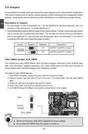
2 2-5 Jumpers For some features needed, users can change the jumper settings on this motherboard to factory default when the BIOS settings were mistakenly modified. Clear CMOS data is simply labeled as BIOS data, date, time information, hardware password...etc.). This will clear CMOS data. 3. Clear 3 2 1 Normal 3 2 (Default... 2. Return the setting to configure new system as described in the power cord to clear CMOS data are : 1. Go to BIOS Setup to its original with pins 2-3 closed Clear CMOS Jumper: CLR_CMOS The motherboard uses CMOS RAM to use the various functions of...
2 2-5 Jumpers For some features needed, users can change the jumper settings on this motherboard to factory default when the BIOS settings were mistakenly modified. Clear CMOS data is simply labeled as BIOS data, date, time information, hardware password...etc.). This will clear CMOS data. 3. Clear 3 2 1 Normal 3 2 (Default... 2. Return the setting to configure new system as described in the power cord to clear CMOS data are : 1. Go to BIOS Setup to its original with pins 2-3 closed Clear CMOS Jumper: CLR_CMOS The motherboard uses CMOS RAM to use the various functions of...
English Manual.
Page 27
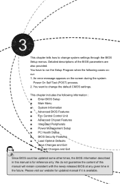
... appears on the screen during the system Power On Self Test (POST) process. 2. We do not guarantee the content of the BIOS parameters are also provided. Please visit our website for updated manual if it is for reference only. You want to change the default... available. This chapter tells how to change system settings through the BIOS Setup menus. You have to run the Setup Program when the following information : ■ Enter BIOS Setup ■ Main Menu ■ System Information ■ Advanced BIOS Features ■ Fox Central Control Unit ■ Advanced Chipset Features...
... appears on the screen during the system Power On Self Test (POST) process. 2. We do not guarantee the content of the BIOS parameters are also provided. Please visit our website for updated manual if it is for reference only. You want to change the default... available. This chapter tells how to change system settings through the BIOS Setup menus. You have to run the Setup Program when the following information : ■ Enter BIOS Setup ■ Main Menu ■ System Information ■ Advanced BIOS Features ■ Fox Central Control Unit ■ Advanced Chipset Features...

English Manual.
Page 28
... main menu is explained below: ► System Information It displays the basic system configuration, such as Serial I /O devices such as BIOS ID, CPU Name, memory size plus system date, time and Floppy drive. Copyright (C) 1985-2006, American Megatrends, Inc. ►... System Information ► PC Health Status ► Advanced BIOS Features ► BIOS Security Features ► Fox Central Control Unit Load Optimal Defaults ► Advanced Chipset Features Save Changes and Exit ► Integrated ...
... main menu is explained below: ► System Information It displays the basic system configuration, such as Serial I /O devices such as BIOS ID, CPU Name, memory size plus system date, time and Floppy drive. Copyright (C) 1985-2006, American Megatrends, Inc. ►... System Information ► PC Health Status ► Advanced BIOS Features ► BIOS Security Features ► Fox Central Control Unit Load Optimal Defaults ► Advanced Chipset Features Save Changes and Exit ► Integrated ...

English Manual.
Page 29
... more memory or I /O cards, less memory ...etc.), still, it may sometimes come out an unstable system. It means, if your system loading is to adjust BIOS setting one by one, trial and error, to find out the best setting for your current system. ► Save Changes and Exit Save setting values..., set to CMOS and exit. ► Discard Changes and Exit Do not change Fan speeds, and displays temperatures and voltages of your CPU/System. ► BIOS Security Features The Supervisor/User password can be loaded through this menu to prevent unauthorized use of your computer.
... more memory or I /O cards, less memory ...etc.), still, it may sometimes come out an unstable system. It means, if your system loading is to adjust BIOS setting one by one, trial and error, to find out the best setting for your current system. ► Save Changes and Exit Save setting values..., set to CMOS and exit. ► Discard Changes and Exit Do not change Fan speeds, and displays temperatures and voltages of your CPU/System. ► BIOS Security Features The Supervisor/User password can be loaded through this menu to prevent unauthorized use of your computer.

English Manual.
Page 30
...Detected] [Not Detected] Floppy A Halt On Keyboard Mouse Floppy [1.44 MB 31/2"] [All Errors, But ...] [Disabled] [Disabled] [Disabled] Model Name BIOS ID : A7DA-S/A7DA : 81BF1P01 Move Enter:Select +/-/:Value F10:Save ESC:Exit F1:General Help F9:Optimized Defaults ► Date (mm:dd:yy) format. Use [+] or ...# is the lower SATA port of SATA5_ESATA. 3 System Information This sub-menu is used to set to [Native IDE], while entering setup, BIOS automatically detects the presence of SATA devices. CMOS Setup Utility - System Information Date (mm:dd:yy) Time (hh:mm:ss) ► ...
...Detected] [Not Detected] Floppy A Halt On Keyboard Mouse Floppy [1.44 MB 31/2"] [All Errors, But ...] [Disabled] [Disabled] [Disabled] Model Name BIOS ID : A7DA-S/A7DA : 81BF1P01 Move Enter:Select +/-/:Value F10:Save ESC:Exit F1:General Help F9:Optimized Defaults ► Date (mm:dd:yy) format. Use [+] or ...# is the lower SATA port of SATA5_ESATA. 3 System Information This sub-menu is used to set to [Native IDE], while entering setup, BIOS automatically detects the presence of SATA devices. CMOS Setup Utility - System Information Date (mm:dd:yy) Time (hh:mm:ss) ► ...

English Manual.
Page 31
User can check this product. ► BIOS ID / BIOS Version It displays the current BIOS ID/version. The size is needed. ► CPU Name It displays the current CPU name. ► Memory This item displays the current memory size. 3 It ... stop for a mouse error if you enabled this item. ► Model Name Model name of this information and discuss with the field service people if a BIOS upgrade is depending on how many memory modules were installed in system halt.
User can check this product. ► BIOS ID / BIOS Version It displays the current BIOS ID/version. The size is needed. ► CPU Name It displays the current CPU name. ► Memory This item displays the current memory size. 3 It ... stop for a mouse error if you enabled this item. ► Model Name Model name of this information and discuss with the field service people if a BIOS upgrade is depending on how many memory modules were installed in system halt.

English Manual.
Page 32
Advanced BIOS Features IDE Detect Time Out MPS Revision PCI Latency Timer Quiet Boot Quick Boot Bootup Num-Lock Floppy Drive Seek ► Boot Device Priority ► ... before they can get access to wait longer before another takes over the set value, the system will actually reduce performance as the default 1.4. Advanced BIOS Features CMOS Setup Utility - MPS version 1.4 adds extended configuration tables for improved support of 64 cycles is used to select the time out value for...
Advanced BIOS Features IDE Detect Time Out MPS Revision PCI Latency Timer Quiet Boot Quick Boot Bootup Num-Lock Floppy Drive Seek ► Boot Device Priority ► ... before they can get access to wait longer before another takes over the set value, the system will actually reduce performance as the default 1.4. Advanced BIOS Features CMOS Setup Utility - MPS version 1.4 adds extended configuration tables for improved support of 64 cycles is used to select the time out value for...
English Manual.
Page 33
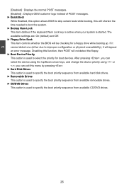
The available settings are: On (default) and Off. ► Floppy Drive Seek This item controls whether the BIOS will be checking for boot devices. If it will appear an error message. Disabling this function, then POST will not detect the floppy. ►.... 26 3 [Disabled] : Displays the normal POST messages. [Enabled] : Displays OEM customer logo instead of POST messages. ► Quick Boot While Enabled, this option allows BIOS to skip certain tests while booting, this will shorten the time needed to specify the boot priority sequence from available removable drives. ► CD/DVD...
The available settings are: On (default) and Off. ► Floppy Drive Seek This item controls whether the BIOS will be checking for boot devices. If it will appear an error message. Disabling this function, then POST will not detect the floppy. ►.... 26 3 [Disabled] : Displays the normal POST messages. [Enabled] : Displays OEM customer logo instead of POST messages. ► Quick Boot While Enabled, this option allows BIOS to skip certain tests while booting, this will shorten the time needed to specify the boot priority sequence from available removable drives. ► CD/DVD...

English Manual.
Page 34
...slot. Copyright (C) 1985-2006, American Megatrends, Inc. Super BIOS Protect function protects your BIOS from virus attack, there is used to its submenu. 27 CIH. ► Auto Detect PCI Clock This option is a BIOS write-protection mechanism provided. 3 Fox Central Control Unit CMOS ...Setup Utility - Fox Central Control Unit Super BIOS Protect Auto Detect PCI Clock ► Smart BIOS ► Fox Intelligent Stepping ► Voltage Options ► CPU...
...slot. Copyright (C) 1985-2006, American Megatrends, Inc. Super BIOS Protect function protects your BIOS from virus attack, there is used to its submenu. 27 CIH. ► Auto Detect PCI Clock This option is a BIOS write-protection mechanism provided. 3 Fox Central Control Unit CMOS ...Setup Utility - Fox Central Control Unit Super BIOS Protect Auto Detect PCI Clock ► Smart BIOS ► Fox Intelligent Stepping ► Voltage Options ► CPU...
English Manual.
Page 35
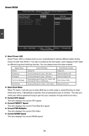
On, 1/3sec. This also prevents user without password trying to get into your motherboard to enter smart boot menu. Smart BIOS CMOS Setup Utility - Smart BIOS Smart Power LED [Enabled] Help Item Smart Boot Menu Current CPU Speed [Enabled] : 2600MHz Options Current FSB/HTT Speed : 1000MHz Current FSB Multiplier : 12.5x ...
On, 1/3sec. This also prevents user without password trying to get into your motherboard to enter smart boot menu. Smart BIOS CMOS Setup Utility - Smart BIOS Smart Power LED [Enabled] Help Item Smart Boot Menu Current CPU Speed [Enabled] : 2600MHz Options Current FSB/HTT Speed : 1000MHz Current FSB Multiplier : 12.5x ...

English Manual.
Page 37
... the reset sequence. It also can improve the stabilization of AMD. Some problems that need to achieve the function, including AMD OverDrive tool and compatible BIOS. But if overclocking is activated, you enabled this function, it . ► CPU-NB HT Link Speed HT stands for short, is supporting this feature. ►...
... the reset sequence. It also can improve the stabilization of AMD. Some problems that need to achieve the function, including AMD OverDrive tool and compatible BIOS. But if overclocking is activated, you enabled this function, it . ► CPU-NB HT Link Speed HT stands for short, is supporting this feature. ►...
English Manual.
Page 41
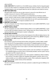
... using a non-ATI PCI Express (PCIe) graphics card, SurroundView is freed for maximum 2D/3D graphics performance. Enabling SurroundView in the BIOS enables the integrated UMA graphics controller, which in turn makes available up to set the UMA and sideport interleave mode. In this mode,...impact display modes (resolution and color depth) or performance. The display mode of each output is controlled independently by default. 3 within the BIOS. [UMA+SIDEPORT]-The SidePort is a 32-bit DDR memory interface that provides multi-graphics controller display capability for both the UMA space ...
... using a non-ATI PCI Express (PCIe) graphics card, SurroundView is freed for maximum 2D/3D graphics performance. Enabling SurroundView in the BIOS enables the integrated UMA graphics controller, which in turn makes available up to set the UMA and sideport interleave mode. In this mode,...impact display modes (resolution and color depth) or performance. The display mode of each output is controlled independently by default. 3 within the BIOS. [UMA+SIDEPORT]-The SidePort is a 32-bit DDR memory interface that provides multi-graphics controller display capability for both the UMA space ...

English Manual.
Page 42
Once this option is enabled, the BIOS can deal with those storage cells. Unganged channels ■ DCT channels A and B operate as a single logical 128-bit DIMM. ■ Offers highest DDR2 bandwidth. ■ ...
Once this option is enabled, the BIOS can deal with those storage cells. Unganged channels ■ DCT channels A and B operate as a single logical 128-bit DIMM. ■ Offers highest DDR2 bandwidth. ■ ...

English Manual.
Page 43
...+/-/:Value F10:Save ESC:Exit F1:General Help F9:Optimized Defaults ► DRAM Timing Mode When both DCTs are enabled in unganged mode, BIOS must initialize the frequency of each DCT in order. A DIMM or a group of DIMMs enters power down mode by asserting the corresponding ... CKE control. A DIMM or a group of DIMMs exits power down mode by deasserting the corresponding clock enable signal when the DRAM controller detects that BIOS programs into the memory 36 DRAM Timing Configuration CMOS Setup Utility - Settings are : [Auto]; [DCT 0]. (appear in AM2 CPU) Settings are two...
...+/-/:Value F10:Save ESC:Exit F1:General Help F9:Optimized Defaults ► DRAM Timing Mode When both DCTs are enabled in unganged mode, BIOS must initialize the frequency of each DCT in order. A DIMM or a group of DIMMs enters power down mode by asserting the corresponding ... CKE control. A DIMM or a group of DIMMs exits power down mode by deasserting the corresponding clock enable signal when the DRAM controller detects that BIOS programs into the memory 36 DRAM Timing Configuration CMOS Setup Utility - Settings are : [Auto]; [DCT 0]. (appear in AM2 CPU) Settings are two...

English Manual.
Page 48
... port 2. SuperIO Configuration SuperIO Configuration Help Item OnBoard Floppy Controller Serial Port1 Address Serial Port2 Address Serial Port2 Mode Serial Port2 Duplex Mode [Enabled] Allows BIOS to Enable [3F8/IRQ4] or disable floppy [2F8/IRQ3] controller. [IrDA] [Half Duplex] Move Enter:Select +/-/:Value F10:Save ESC:Exit F1:General Help F9...
... port 2. SuperIO Configuration SuperIO Configuration Help Item OnBoard Floppy Controller Serial Port1 Address Serial Port2 Address Serial Port2 Mode Serial Port2 Duplex Mode [Enabled] Allows BIOS to Enable [3F8/IRQ4] or disable floppy [2F8/IRQ3] controller. [IrDA] [Half Duplex] Move Enter:Select +/-/:Value F10:Save ESC:Exit F1:General Help F9...


