
Multi language Manual
Page 4
... 31 Chapter 3 Directions for Bundled Software FOX ONE 33 FOX LiveUpdate 36 FOX LOGO 38 FOX DMI 39 Advanced Chipset Features 26 5. Integrated Peripherals 27 6. Power Management Setup 28 7. Central Control Unit 24 3. Load Optimal Defaults 31 11. Save Changes and Exit 31 12. PnP/PCI Configuration 29 8. Standard CMOS Features...
... 31 Chapter 3 Directions for Bundled Software FOX ONE 33 FOX LiveUpdate 36 FOX LOGO 38 FOX DMI 39 Advanced Chipset Features 26 5. Integrated Peripherals 27 6. Power Management Setup 28 7. Central Control Unit 24 3. Load Optimal Defaults 31 11. Save Changes and Exit 31 12. PnP/PCI Configuration 29 8. Standard CMOS Features...
Multi language Manual
Page 5
Attention: Please visit the Foxconn global English website (http://www. Ensure that the DC power supply is suggested to select high-quality, certified fans in the future. Attention: Since BIOS programs are just for your system will remain consistent with ... will operate normally while over -clock capacity of your system or memory module. Attention: The pictures of this motherboard. It is turned off the DC power supply may result in this manual are upgrated from time to time, the BIOS description in serious damage to switch off before inserting or removing...
Attention: Please visit the Foxconn global English website (http://www. Ensure that the DC power supply is suggested to select high-quality, certified fans in the future. Attention: Since BIOS programs are just for your system will remain consistent with ... will operate normally while over -clock capacity of your system or memory module. Attention: The pictures of this motherboard. It is turned off the DC power supply may result in this manual are upgrated from time to time, the BIOS description in serious damage to switch off before inserting or removing...

Multi language Manual
Page 6
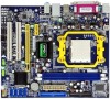
This series of motherboard is one of our new products, and offers superior performance, reliability and quality, at a reasonable price. This chapter includes the following information: v Specifications v Jumpers 1 Chapter Thank you for users. This motherboard adopts the advanced AMD 690V+SB600 chipset, providing a computer platform with high integration, powerful compatibility and high performance-price ratio for buying Foxconn's A6VMX Series motherboard.
This series of motherboard is one of our new products, and offers superior performance, reliability and quality, at a reasonable price. This chapter includes the following information: v Specifications v Jumpers 1 Chapter Thank you for users. This motherboard adopts the advanced AMD 690V+SB600 chipset, providing a computer platform with high integration, powerful compatibility and high performance-price ratio for buying Foxconn's A6VMX Series motherboard.

Multi language Manual
Page 8
...;1 x S/PDIF_OUT header (optional) ·1 x TPM header (optional) ·1 x TV_OUT header ·1 x COM2 port header (optional) ·1 x Front Audio connector ·1 x 24-pin ATX Power Connector ·1 x 4-pin AUX Power Connector ·1 x IrDA header ·1 x CPU Fan connector ·1 x System Fan connector ·1 x NB Fan connector (optional) ·Front panel connector ·Driver...
...;1 x S/PDIF_OUT header (optional) ·1 x TPM header (optional) ·1 x TV_OUT header ·1 x COM2 port header (optional) ·1 x Front Audio connector ·1 x 24-pin ATX Power Connector ·1 x 4-pin AUX Power Connector ·1 x IrDA header ·1 x CPU Fan connector ·1 x System Fan connector ·1 x NB Fan connector (optional) ·Front panel connector ·Driver...

Multi language Manual
Page 23
... wake-up the computer from pins 2-3 (default) to pins 1-2. USBPW R1 is for the internal USB ports. 2. otherwise, the system will not power up the computer from S1 sleep mode using the connected USB devices. Attention The jumpers on the motherboard, pin 1 can provide 500mA on pins 1-2 ... to clear the data in this manual, pin 1 is for the rear USB connectors, USBPW R2 is simply labeled as follows: 1. Plug the power cord and turn on USB Devices" to default setup, please do as "1". You should read the following content carefully prior to setup jumpers. Chapter ...
... wake-up the computer from pins 2-3 (default) to pins 1-2. USBPW R1 is for the internal USB ports. 2. otherwise, the system will not power up the computer from S1 sleep mode using the connected USB devices. Attention The jumpers on the motherboard, pin 1 can provide 500mA on pins 1-2 ... to clear the data in this manual, pin 1 is for the rear USB connectors, USBPW R2 is simply labeled as follows: 1. Plug the power cord and turn on USB Devices" to default setup, please do as "1". You should read the following content carefully prior to setup jumpers. Chapter ...

Multi language Manual
Page 24
Set the jumper to pins 2-3(+5VSB) to "Enabled". 1 +5V (Default) 1 +5VSB KB/MSPW R 19 Chapter 1 Main Features Keyboard and Mouse Jumper: KB/MS_PWR This jumper allows you to enable or disable the Keyboard and Mouse wake-up the computer from sleep modes when you press a key on the keyboard or click the mouse, and a corresponding setting must be set in BIOS as below: Set "CMOS Setup"=>"Power Management Setup"=> "Wake on PS2 Keyboard"and "W ake on PS2Mouse" to wake up feature.
Set the jumper to pins 2-3(+5VSB) to "Enabled". 1 +5V (Default) 1 +5VSB KB/MSPW R 19 Chapter 1 Main Features Keyboard and Mouse Jumper: KB/MS_PWR This jumper allows you to enable or disable the Keyboard and Mouse wake-up the computer from sleep modes when you press a key on the keyboard or click the mouse, and a corresponding setting must be set in BIOS as below: Set "CMOS Setup"=>"Power Management Setup"=> "Wake on PS2 Keyboard"and "W ake on PS2Mouse" to wake up feature.

Multi language Manual
Page 25
... Setup Program when the following information: v Enter BIOS Setup v Main Menu v Standard CMOS Features v Central Control Unit v Advanced BIOS Features v Advanced Chipset Features v Integrated Peripherals v Power Management Setup v PnP/PCI Configuration v PC Health Status v BIOS Security Features v Load Optimal Defaults v Save Changes and Exit v Discard Changes and Exit 20
... Setup Program when the following information: v Enter BIOS Setup v Main Menu v Standard CMOS Features v Central Control Unit v Advanced BIOS Features v Advanced Chipset Features v Integrated Peripherals v Power Management Setup v PnP/PCI Configuration v PC Health Status v BIOS Security Features v Load Optimal Defaults v Save Changes and Exit v Discard Changes and Exit 20

Multi language Manual
Page 26
... The special features can be set up through this menu. 3. Main Menu The main menu displays a list of the screen during the POST (Power On Self Test), press key to enter the BIOS CMOS Setup Utility. Use the arrow keys to highlight an item, and execute the item by...available. Note: W e do not suggest that are explained as below: 1. Advanced BIOS Features The advanced system features can be set up through this menu. 2. Power on the computer, when the following message briefly appears at the bottom of options that you make. Chapter 2 BIOS Description Enter BIOS Setup The BIOS...
... The special features can be set up through this menu. 3. Main Menu The main menu displays a list of the screen during the POST (Power On Self Test), press key to enter the BIOS CMOS Setup Utility. Use the arrow keys to highlight an item, and execute the item by...available. Note: W e do not suggest that are explained as below: 1. Advanced BIOS Features The advanced system features can be set up through this menu. 2. Power on the computer, when the following message briefly appears at the bottom of options that you make. Chapter 2 BIOS Description Enter BIOS Setup The BIOS...

Multi language Manual
Page 27
... Features Menu This item shows the version and build date of your PC. 9. BIOS Security Features BIOS Secutiry configuration can set up all the Power Management events related items. 7. Discard Changes and Exit Abandon all CMOS value changes and exit setup. 1.Standard BIOS Features This sub-menu is ...used to CMOS and exit setup. 12. Power Management Setup Through this menu. 8.PC Health Status This menu will display the current status of the AMIBIOS. 1.2 System Time/Date This item ...
... Features Menu This item shows the version and build date of your PC. 9. BIOS Security Features BIOS Secutiry configuration can set up all the Power Management events related items. 7. Discard Changes and Exit Abandon all CMOS value changes and exit setup. 1.Standard BIOS Features This sub-menu is ...used to CMOS and exit setup. 12. Power Management Setup Through this menu. 8.PC Health Status This menu will display the current status of the AMIBIOS. 1.2 System Time/Date This item ...

Multi language Manual
Page 28
..., including [none], [360K, 51/4 in], [1.2M, 51/4in], [720K, 31/2 in], [1.44M, 31/2 in] and [2.88 M, 31/2 in system halt on. This is detected during powering up by users. Take "Primary IDE Master" for the IDE device that you to set them . 23 Make sure to set to active. 1.4 Floppy A This...
..., including [none], [360K, 51/4 in], [1.2M, 51/4in], [720K, 31/2 in], [1.44M, 31/2 in] and [2.88 M, 31/2 in system halt on. This is detected during powering up by users. Take "Primary IDE Master" for the IDE device that you to set them . 23 Make sure to set to active. 1.4 Floppy A This...
Multi language Manual
Page 30
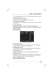
NOTE: The Spread Spectrum function can influence the EMI (Electromagnetic Interference)degree. 2.6 FOXCONN Feature FOXCONN Feature Menu 2.6.1 CPU Voltage Control Use this function, the power LED status can show the system status of PCIE Graphics card. "Disabled" is the default value. 2.6.3 NB Voltage ...Clock (MHz) This item allows you may adjust the North Bridge volatge manually. 2.6.4 Smart Power LED Smart debug LED function within power LED. If it detect the memory or graphics cards fail , the power LED will be grayed-out. 2.1.2 CPU/HT Reference Clock (MHz) Use this item, you...
NOTE: The Spread Spectrum function can influence the EMI (Electromagnetic Interference)degree. 2.6 FOXCONN Feature FOXCONN Feature Menu 2.6.1 CPU Voltage Control Use this function, the power LED status can show the system status of PCIE Graphics card. "Disabled" is the default value. 2.6.3 NB Voltage ...Clock (MHz) This item allows you may adjust the North Bridge volatge manually. 2.6.4 Smart Power LED Smart debug LED function within power LED. If it detect the memory or graphics cards fail , the power LED will be grayed-out. 2.1.2 CPU/HT Reference Clock (MHz) Use this item, you...

Multi language Manual
Page 31
... priority sequence from the availabe devices. 3.3 Quick Boot This item allows you will search for the Numlock.the default value is used to select the power-on state for floppy disk drive at boot time. 3.6 Bootup Num-Lock Use this item to enable or disable the quiet boot. [Disabled]: Displays normal...
... priority sequence from the availabe devices. 3.3 Quick Boot This item allows you will search for the Numlock.the default value is used to select the power-on state for floppy disk drive at boot time. 3.6 Bootup Num-Lock Use this item to enable or disable the quiet boot. [Disabled]: Displays normal...
Multi language Manual
Page 32
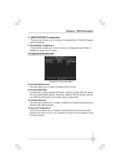
... the parameters of Internal Grapgics and PCI Express. 4.2 NorthBridge Configuration This sub-menu allows you to set the memory configuration and enable or disable the power down function. 5.Integrated Peripherals Integrated Peripherals Menu 5.1OnChip SATA Channel This item allows you to enable or disable SATA channel. 5.2 OnChip SATA Type Use this...
... the parameters of Internal Grapgics and PCI Express. 4.2 NorthBridge Configuration This sub-menu allows you to set the memory configuration and enable or disable the power down function. 5.Integrated Peripherals Integrated Peripherals Menu 5.1OnChip SATA Channel This item allows you to enable or disable SATA channel. 5.2 OnChip SATA Type Use this...
Multi language Manual
Page 33
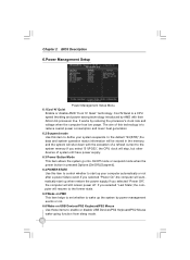
... this item to control whether to enable or disable USB Devices/PS2 Keyboard/PS2 Mouse wake-uping function from sleep mode. 28 It works by power management events or not. 6.6 Wake on PME This item helps to set whether to define your computer automatically or not after... system operation status information will be stored in the memory, and the system will shut down with their Athlon 64 processor line. If you selected "Power Off", the computer will resume to the former state. 6.5 Wake on USB Devices/PS2 Keyboard/PS2 Mouse Use these items to start up the system...
... this item to control whether to enable or disable USB Devices/PS2 Keyboard/PS2 Mouse wake-uping function from sleep mode. 28 It works by power management events or not. 6.6 Wake on PME This item helps to set whether to define your computer automatically or not after... system operation status information will be stored in the memory, and the system will shut down with their Athlon 64 processor line. If you selected "Power Off", the computer will resume to the former state. 6.5 Wake on USB Devices/PS2 Keyboard/PS2 Mouse Use these items to start up the system...

Multi language Manual
Page 38
... in abnormal status, the alert lamp color will simplify the interface to monitor if your system is in healthy status, the alert lamp color is a powerful utility for easily modifying system settings. And if the system is in the healthy status at any time. 33 Switch Button Click this button, it...
... in abnormal status, the alert lamp color will simplify the interface to monitor if your system is in healthy status, the alert lamp color is a powerful utility for easily modifying system settings. And if the system is in the healthy status at any time. 33 Switch Button Click this button, it...
Multi language Manual
Page 43
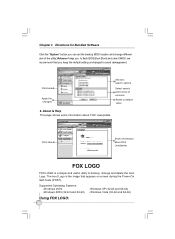
... FOX LOGO FOX LOGO is the image that you keep the default setting unchanged to backup, change different skin of ver s i on screen during the Power-On Self-Tests (POST). Supported Operating Systems: -W indows 2000 -W indows 2003 (32-bit and 64-bit) -Windows XP (32-bit and 64-bit) -W indows Vista...
... FOX LOGO FOX LOGO is the image that you keep the default setting unchanged to backup, change different skin of ver s i on screen during the Power-On Self-Tests (POST). Supported Operating Systems: -W indows 2000 -W indows 2003 (32-bit and 64-bit) -Windows XP (32-bit and 64-bit) -W indows Vista...


