
Product Manual
Page 2
... and workmanship under normal use outside the product's specified rating, or normal wear and tear of mechanical components, Fluke will provide an estimate of repair costs and obtain authorization before commencing the work. Parts, product repairs, and services are warranted for Fluke products online at Fluke's option, to refund of the purchase price, free of charge repair, or replacement of a Fluke authorized reseller, and does...
... and workmanship under normal use outside the product's specified rating, or normal wear and tear of mechanical components, Fluke will provide an estimate of repair costs and obtain authorization before commencing the work. Parts, product repairs, and services are warranted for Fluke products online at Fluke's option, to refund of the purchase price, free of charge repair, or replacement of a Fluke authorized reseller, and does...
Product Manual
Page 7
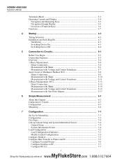
...5-13 Measurement with Shunt 5-14 Measurement with Voltage and Current Transducer 5-15 Measurement with Star Point Adapter 5-17 6 Simple Measurement 6-1 About this Chapter 6-3 Connection to Circuits 6-3 Configuration ...6-3 Measuring ...6-4 7 Configuration 7-1 Set Up for Measuring 7-3 Configuration ...7-3 Five Steps...7-4 Call up General Setup and System Information Screen 7-4 General Setup 7-4 System Information Screen 7-4 Load Configuration 7-5 Load Configuration (Optional 7-5 Modify Loaded Configurations 7-5 Configure Method 7-5 Configure Data Transfer to Printer and PC...
...5-13 Measurement with Shunt 5-14 Measurement with Voltage and Current Transducer 5-15 Measurement with Star Point Adapter 5-17 6 Simple Measurement 6-1 About this Chapter 6-3 Connection to Circuits 6-3 Configuration ...6-3 Measuring ...6-4 7 Configuration 7-1 Set Up for Measuring 7-3 Configuration ...7-3 Five Steps...7-4 Call up General Setup and System Information Screen 7-4 General Setup 7-4 System Information Screen 7-4 Load Configuration 7-5 Load Configuration (Optional 7-5 Modify Loaded Configurations 7-5 Configure Method 7-5 Configure Data Transfer to Printer and PC...
Product Manual
Page 8
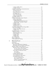
...) Configure GPIB Address 7-8 Configure Ethernet 7-8 Configure Average Time and Synchronization 7-9 Timing & Sync Setup 7-9 Set Average Time 7-10 Select Synchronization Source 7-11 Set Trigger Level 7-11 Select Slope Direction 7-12 Select Low-Pass Filter 7-12 Configure Signal Output 7-12 Adjust Date and Time 7-13 Configure Current and Voltage Channels 7-13 Current Channel Setup 7-14 Configure Input Range 7-15 Automatic Range Adjustment (Auto 7-15 Manual Range Adjustment (Range 7-15 Configure Scale...
...) Configure GPIB Address 7-8 Configure Ethernet 7-8 Configure Average Time and Synchronization 7-9 Timing & Sync Setup 7-9 Set Average Time 7-10 Select Synchronization Source 7-11 Set Trigger Level 7-11 Select Slope Direction 7-12 Select Low-Pass Filter 7-12 Configure Signal Output 7-12 Adjust Date and Time 7-13 Configure Current and Voltage Channels 7-13 Current Channel Setup 7-14 Configure Input Range 7-15 Automatic Range Adjustment (Auto 7-15 Manual Range Adjustment (Range 7-15 Configure Scale...

Product Manual
Page 17
... Data". • During operation, ensure that all warranty. Improper use the device for fault-free operation is limited to the admissible conditions laid down in IEC 61010-1/ 2nd edition. Safe Operation • Ensure that the cooling vents are familiar with the installation, assembly, connection, inspection of connections, and operation of the analyzer and who have read and fully understood the Operators Manual and safety instructions...
... Data". • During operation, ensure that all warranty. Improper use the device for fault-free operation is limited to the admissible conditions laid down in IEC 61010-1/ 2nd edition. Safe Operation • Ensure that the cooling vents are familiar with the installation, assembly, connection, inspection of connections, and operation of the analyzer and who have read and fully understood the Operators Manual and safety instructions...

Product Manual
Page 18
... the protective earth terminal and the protective earth of the measuring circuit. NORMA 4000/5000 Operators Manual Electrical Connections • Ensure that the power and connecting cables used in conjunction with the device are in proper working order. • Ensure that its power cable is accessible at all accessories used with the device are in proper working order and clean. • Install the...
... the protective earth terminal and the protective earth of the measuring circuit. NORMA 4000/5000 Operators Manual Electrical Connections • Ensure that the power and connecting cables used in conjunction with the device are in proper working order. • Ensure that its power cable is accessible at all accessories used with the device are in proper working order and clean. • Install the...

Product Manual
Page 19
... device or specifically available as regards the safe operation of the device, immediately shut down the unit and the respective accessories, secure them to . Do not carry out any repairs and do not replace any damage to the housing, controls, power cable, connecting leads, or connected devices, immediately disconnect the unit from the power supply. • If you detect any component parts of...
... device or specifically available as regards the safe operation of the device, immediately shut down the unit and the respective accessories, secure them to . Do not carry out any repairs and do not replace any damage to the housing, controls, power cable, connecting leads, or connected devices, immediately disconnect the unit from the power supply. • If you detect any component parts of...
Product Manual
Page 25
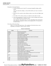
... Delete configuration View details of a measured value Set frequency analysis filter View system information and version number of unit firmware Reduce brightness of display Increase brightness of display View linear/logarithmic scale Load configuration View table with harmonics Adjust zero (with cursor keys) View rms values or H01 fundamental Save configuration Adjust scales of axes (with cursor keys) View electrical work reference power or recuperated power Set electrical work integration...
... Delete configuration View details of a measured value Set frequency analysis filter View system information and version number of unit firmware Reduce brightness of display Increase brightness of display View linear/logarithmic scale Load configuration View table with harmonics Adjust zero (with cursor keys) View rms values or H01 fundamental Save configuration Adjust scales of axes (with cursor keys) View electrical work reference power or recuperated power Set electrical work integration...
Product Manual
Page 28
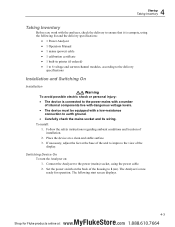
... the back of installation. 2. Set the power switch on ). 4 Startup Taking Inventory Taking Inventory Before you work with a low-resistance connection to earth ground. • Carefully check the mains socket and its wiring. The following list and the delivery specifications: • 1 Power Analyzer • 1 Operators Manual • 1 mains (power) cable • 1 calibration certificate • 1 built-in printer (if ordered) • 1 to 6 voltage and current channel modules...
... the back of installation. 2. Set the power switch on ). 4 Startup Taking Inventory Taking Inventory Before you work with a low-resistance connection to earth ground. • Carefully check the mains socket and its wiring. The following list and the delivery specifications: • 1 Power Analyzer • 1 Operators Manual • 1 mains (power) cable • 1 calibration certificate • 1 built-in printer (if ordered) • 1 to 6 voltage and current channel modules...

Product Manual
Page 36
... instructions regarding the sequence of connection (see Chapter 7, "Configuration." Note The W2 mode is only available for 3-wire networks, see Figure 5-5. XW Warning To avoid possible electric shock or personal injury: • Risk of injury when touching connections, internal circuits, and measuring devices that there is not acceptable for measurements on inverters, as I1+I2+I3 must be used...
... instructions regarding the sequence of connection (see Chapter 7, "Configuration." Note The W2 mode is only available for 3-wire networks, see Figure 5-5. XW Warning To avoid possible electric shock or personal injury: • Risk of injury when touching connections, internal circuits, and measuring devices that there is not acceptable for measurements on inverters, as I1+I2+I3 must be used...

Product Manual
Page 45
However, in high frequency switching electronics systems such as drives, inverters, and UPS, this error, use the star point adapter, see Figure 5-11. 5 Connection to Circuits 3-Phase Measurement (W3) Measurement with Star Point Adapter In systems with Star Point Adapter esn078.eps 5-17 MyFlukeStore Shop for this method has additional errors due to high frequency components being shunted to the HI terminal and the LO...
However, in high frequency switching electronics systems such as drives, inverters, and UPS, this error, use the star point adapter, see Figure 5-11. 5 Connection to Circuits 3-Phase Measurement (W3) Measurement with Star Point Adapter In systems with Star Point Adapter esn078.eps 5-17 MyFlukeStore Shop for this method has additional errors due to high frequency components being shunted to the HI terminal and the LO...
Product Manual
Page 52
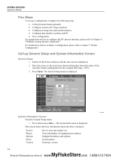
.../5000 Operators Manual Five Steps To set up a configuration, complete the following , 1:W3). 3. This screen shows the basic information about the Power Analyzer: System Phases Options Serial Version Device type and sample rate Type and number of the currently loaded configuration (in the example following steps: • Call up General Setup (optional) • Configure current and voltage channels • Configure average time and synchronization • Configure data transfer...
.../5000 Operators Manual Five Steps To set up a configuration, complete the following , 1:W3). 3. This screen shows the basic information about the Power Analyzer: System Phases Options Serial Version Device type and sample rate Type and number of the currently loaded configuration (in the example following steps: • Call up General Setup (optional) • Configure current and voltage channels • Configure average time and synchronization • Configure data transfer...

Product Manual
Page 53
... power measurement as described in 3-wire/3-phase power systems. For more details, see Chapter 3, "Operating Controls and Display"): RS → RS232, GP → IEEE488, EN → Ethernet, US → USB 7-5 MyFlukeStore Shop for Fluke products online at: www. .com 1.888.610.7664 7 Configuration Load Configuration Load Configuration Note If you have not set up and saved a new configuration before, you must configure the parameters for the data...
... power measurement as described in 3-wire/3-phase power systems. For more details, see Chapter 3, "Operating Controls and Display"): RS → RS232, GP → IEEE488, EN → Ethernet, US → USB 7-5 MyFlukeStore Shop for Fluke products online at: www. .com 1.888.610.7664 7 Configuration Load Configuration Load Configuration Note If you have not set up and saved a new configuration before, you must configure the parameters for the data...

Product Manual
Page 56
... those of line RS232. 4. A list with the device by its standard Remote Control command set rate, you might consider adjusting the RS232 settings for the Power Analyzer to the field in line RS232. 2. IP subnet mask address 0.... Telnet communicates with available addresses is a widely used simultaneously in line LAN and press Enter. Configure GPIB Address The general-purpose interface bus (GPIB) port is displayed. 2. A window with...
... those of line RS232. 4. A list with the device by its standard Remote Control command set rate, you might consider adjusting the RS232 settings for the Power Analyzer to the field in line RS232. 2. IP subnet mask address 0.... Telnet communicates with available addresses is a widely used simultaneously in line LAN and press Enter. Configure GPIB Address The general-purpose interface bus (GPIB) port is displayed. 2. A window with...
Product Manual
Page 58
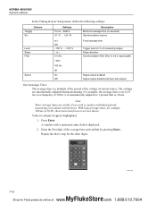
...it is automatically adjusted to 1 period, that is, 20 ms. Note Short average times are useful, if you wish to 19 ms; The settings are not shown. With long average times, for example 300 ms at a frequency of the...Fluke products online at Sync Ext output) Set Average Time The average time is displayed. 2. A window with a numerical entry field is a multiple of the period of the voltage of current source. esn021.eps 7-10 MyFlukeStore Shop for the other digits. NORMA 4000/5000 Operators Manual In the Timing & Sync Setup menu, define the following settings: Column Tavg[s] Src Settings...
...it is automatically adjusted to 1 period, that is, 20 ms. Note Short average times are useful, if you wish to 19 ms; The settings are not shown. With long average times, for example 300 ms at a frequency of the...Fluke products online at Sync Ext output) Set Average Time The average time is displayed. 2. A window with a numerical entry field is a multiple of the period of the voltage of current source. esn021.eps 7-10 MyFlukeStore Shop for the other digits. NORMA 4000/5000 Operators Manual In the Timing & Sync Setup menu, define the following settings: Column Tavg[s] Src Settings...

Product Manual
Page 69
...display. 3. Line En Clr ON OFF MAN AUTO Settings Description Integration function active Integration function inactive Clear manual Auto clear at column State. Save the configuration settings by pressing the SAVE function key. The integrations function is displayed. 2. Configure the other values...function is enabled (ON) in the Integration Setup menu at start conditions Configure data reset / set stop conditions Select first three values Select next three values Menu Integration Setup is now shown on the screen. A dialog window showing the selectable values is now enabled. ...
...display. 3. Line En Clr ON OFF MAN AUTO Settings Description Integration function active Integration function inactive Clear manual Auto clear at column State. Save the configuration settings by pressing the SAVE function key. The integrations function is displayed. 2. Configure the other values...function is enabled (ON) in the Integration Setup menu at start conditions Configure data reset / set stop conditions Select first three values Select next three values Menu Integration Setup is now shown on the screen. A dialog window showing the selectable values is now enabled. ...

Product Manual
Page 75
... Connect Power Analyzer to save and load as the configuration is set and the device is switched on. and direct-current input) can define more specific settings to the mains (power) socket. 1. Note If measurements with an external shunt or probe are available for loading quick setups. The Power Analyzer calculates rms values, real, apparent and reactive power, and other derived values. Default settings...
... Connect Power Analyzer to save and load as the configuration is set and the device is switched on. and direct-current input) can define more specific settings to the mains (power) socket. 1. Note If measurements with an external shunt or probe are available for loading quick setups. The Power Analyzer calculates rms values, real, apparent and reactive power, and other derived values. Default settings...

Product Manual
Page 90
... view a different measure parameter, press function key Detail again. 5. To change the scale of 5 ms. 2. To view a different channel or different measured values in the measuring system. Press function key Offset. 2. Press measuring keys Σ or 1...n and WAV to call up the values, for Fluke products online at channels 1 to confirm. This function is shown. NORMA 4000/5000 Operators Manual...
... view a different measure parameter, press function key Detail again. 5. To change the scale of 5 ms. 2. To view a different channel or different measured values in the measuring system. Press function key Offset. 2. Press measuring keys Σ or 1...n and WAV to call up the values, for Fluke products online at channels 1 to confirm. This function is shown. NORMA 4000/5000 Operators Manual...

Product Manual
Page 105
... transient processes. Print Measurements • Connect a printer, unless using a NORMA 5000 with the device. More information on a computer and sending keyboard and mouse events from the computer to the device. Note Measuring key Storage works only in the background of RealVNC Ltd. Because they may support different sets of the respective software product. 8 Measuring Process Save and...
... transient processes. Print Measurements • Connect a printer, unless using a NORMA 5000 with the device. More information on a computer and sending keyboard and mouse events from the computer to the device. Note Measuring key Storage works only in the background of RealVNC Ltd. Because they may support different sets of the respective software product. 8 Measuring Process Save and...

Product Manual
Page 118
...) Output voltage Allowable external voltage Additional error Temperature coefficient Output rate Resolution Rise time Response time maximum ±10.3 V; maximum load 5 mA, short-circuit protected, shared LO connection to measure the frequency at HI input ±(0.15 % of AVG + 0.05 % of rotation are only used for the detection of the sense of FV), final value FV = 10 V Input Configured as...
...) Output voltage Allowable external voltage Additional error Temperature coefficient Output rate Resolution Rise time Response time maximum ±10.3 V; maximum load 5 mA, short-circuit protected, shared LO connection to measure the frequency at HI input ±(0.15 % of AVG + 0.05 % of rotation are only used for the detection of the sense of FV), final value FV = 10 V Input Configured as...

Product Manual
Page 145
NORMA 4000/5000 Operators Manual Service General The Power Analyzer may only be serviced by specialized service workshops authorized by 12-12 MyFlukeStore Shop for Fluke products online at: www. .com 1.888.610.7664
NORMA 4000/5000 Operators Manual Service General The Power Analyzer may only be serviced by specialized service workshops authorized by 12-12 MyFlukeStore Shop for Fluke products online at: www. .com 1.888.610.7664


