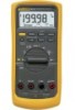

FE 83V & 87V Users Manual
Page 2
...sent for product repaired or replaced in transit. Thereafter, for the lifetime of the DMM, Fluke will pay return transportation for repair elsewhere. Fluke will, at its lifetime. Fluke will replace the LCD for damage in -warranty. Since some states do not allow the ...mechanical components. THIS WARRANTY IS YOUR ONLY REMEDY. This warranty does not cover fuses, disposable batteries, damage from defects in one country is not transferable. Fluke Corporation Fluke Europe B.V. Lifetime Limited Warranty Each Fluke 20, 70, 80, 170 and 180 Series DMM will be at the applicable...
...sent for product repaired or replaced in transit. Thereafter, for the lifetime of the DMM, Fluke will pay return transportation for repair elsewhere. Fluke will, at its lifetime. Fluke will replace the LCD for damage in -warranty. Since some states do not allow the ...mechanical components. THIS WARRANTY IS YOUR ONLY REMEDY. This warranty does not cover fuses, disposable batteries, damage from defects in one country is not transferable. Fluke Corporation Fluke Europe B.V. Lifetime Limited Warranty Each Fluke 20, 70, 80, 170 and 180 Series DMM will be at the applicable...
FE 83V & 87V Users Manual
Page 4
80 Series V Users Manual Measuring AC or DC Current 24 Measuring Frequency 27 Measuring Duty Cycle 29 Determining Pulse Width 30 Bar Graph...30 Zoom Mode (Power Up Option Only 31 Uses for the Zoom Mode 31 HiRes Mode (Model 87) ...31 MIN MAX Recording Mode 32 Smooth Feature (Power Up Option Only 32 AutoHOLD Mode...34 Relative Mode ...34 Maintenance...35 General Maintenance...35 Fuse Test ...35 Replacing the Battery...36 Replacing the Fuses ...37 Service and Parts...37 Specifications ...43 Detailed Specifications 44 ii
80 Series V Users Manual Measuring AC or DC Current 24 Measuring Frequency 27 Measuring Duty Cycle 29 Determining Pulse Width 30 Bar Graph...30 Zoom Mode (Power Up Option Only 31 Uses for the Zoom Mode 31 HiRes Mode (Model 87) ...31 MIN MAX Recording Mode 32 Smooth Feature (Power Up Option Only 32 AutoHOLD Mode...34 Relative Mode ...34 Maintenance...35 General Maintenance...35 Fuse Test ...35 Replacing the Battery...36 Replacing the Fuses ...37 Service and Parts...37 Specifications ...43 Detailed Specifications 44 ii

FE 83V & 87V Users Manual
Page 7
Measuring AC and DC Voltage 14 3. Measuring Current...25 9. Components of Figures Figure Title Page 1. Testing the Current Fuses ...36 11. Low Pass Filter ...15 4. Testing for Continuity...17 5. Measuring Resistance ...19 6. Battery and Fuse Replacement 38 12. Testing a Diode...23 8. List of Duty Cycle Measurements 29 10. Measuring Capacitance...21 7. Replaceable Parts ...41 v Display Features (Model 87) ...11 2.
Measuring AC and DC Voltage 14 3. Measuring Current...25 9. Components of Figures Figure Title Page 1. Testing the Current Fuses ...36 11. Low Pass Filter ...15 4. Testing for Continuity...17 5. Measuring Resistance ...19 6. Battery and Fuse Replacement 38 12. Testing a Diode...23 8. List of Duty Cycle Measurements 29 10. Measuring Capacitance...21 7. Replaceable Parts ...41 v Display Features (Model 87) ...11 2.

FE 83V & 87V Users Manual
Page 11
... use the Meter. • Do not apply more than what is indicated may be present. These voltages pose a shock hazard. • Use only the replacement fuses specified by the manual. • Use the proper terminals, function, and range for measurements. • Avoid working with the circuit. Safety Information • When making...
... use the Meter. • Do not apply more than what is indicated may be present. These voltages pose a shock hazard. • Use only the replacement fuses specified by the manual. • Use the proper terminals, function, and range for measurements. • Avoid working with the circuit. Safety Information • When making...

FE 83V & 87V Users Manual
Page 12
80 Series V Users Manual WCaution To avoid possible damage to the Meter or to the equipment under test, follow these guidelines: • Disconnect circuit power and discharge all high-voltage capacitors before testing resistance, continuity, diodes, or capacitance. • Use the proper terminals, function, and range for all measurements. • Before measuring current, check the Meter's fuses. (See "Fuse Test".) 4
80 Series V Users Manual WCaution To avoid possible damage to the Meter or to the equipment under test, follow these guidelines: • Disconnect circuit power and discharge all high-voltage capacitors before testing resistance, continuity, diodes, or capacitance. • Use the proper terminals, function, and range for all measurements. • Before measuring current, check the Meter's fuses. (See "Fuse Test".) 4

FE 83V & 87V Users Manual
Page 13
... short branch circuits, and lighting systems in large buildings. Low battery when displayed. Electrical Symbols B AC (Alternating Current) F DC (Direct Current) X Hazardous voltage J I P Earth ground Fuse Conforms to relevant Canadian Standards Association directives. Safety Information Table 1. See Manual. Battery. W M R Risk of Danger.
... short branch circuits, and lighting systems in large buildings. Low battery when displayed. Electrical Symbols B AC (Alternating Current) F DC (Direct Current) X Hazardous voltage J I P Earth ground Fuse Conforms to relevant Canadian Standards Association directives. Safety Information Table 1. See Manual. Battery. W M R Risk of Danger.

FE 83V & 87V Users Manual
Page 21
... voltage, continuity, resistance, capacitance, or diode values when the leads are accurate for 30 minutes. The Meter's voltage ranges are testing and blow the Meter's fuse. Making Measurements W Caution Placing the probes across (in parallel with the Meter. To measure ac or dc voltage, refer to take measurements with ) a powered circuit...
... voltage, continuity, resistance, capacitance, or diode values when the leads are accurate for 30 minutes. The Meter's voltage ranges are testing and blow the Meter's fuse. Making Measurements W Caution Placing the probes across (in parallel with the Meter. To measure ac or dc voltage, refer to take measurements with ) a powered circuit...

FE 83V & 87V Users Manual
Page 22
... Peak MIN MAX 4½ DIGITS 1 Second ˚C/˚F RANGE REL mV V AutoHOLD Hz % mA A LO V A OFF A mA A COM V 10A MAX FUSED 400mA FUSED Switch Box 87 V TRUE RMS MULTIMETER DC Voltage mV V MIN MAX Peak MIN MAX 4½ DIGITS 1 Second ˚C/˚F RANGE REL mV V AutoHOLD Hz % ...mA A LO V A OFF A mA A COM V 10A MAX FUSED 400mA FUSED + aom2f.eps Figure 2. Measuring AC and DC Voltage In most cases, the error is negligible (0.1% or less) if the circuit impedance is 10 kΩ (10...
... Peak MIN MAX 4½ DIGITS 1 Second ˚C/˚F RANGE REL mV V AutoHOLD Hz % mA A LO V A OFF A mA A COM V 10A MAX FUSED 400mA FUSED Switch Box 87 V TRUE RMS MULTIMETER DC Voltage mV V MIN MAX Peak MIN MAX 4½ DIGITS 1 Second ˚C/˚F RANGE REL mV V AutoHOLD Hz % ...mA A LO V A OFF A mA A COM V 10A MAX FUSED 400mA FUSED + aom2f.eps Figure 2. Measuring AC and DC Voltage In most cases, the error is negligible (0.1% or less) if the circuit impedance is 10 kΩ (10...

FE 83V & 87V Users Manual
Page 25
Testing for Continuity aom4f.eps 17 For in-circuit tests, turn circuit power off. 87 V TRUE RMS MULTIMETER 4½ DIGITS 1 Second MIN MAX Peak MIN MAX ˚C/˚F RANGE REL mV V AutoHOLD Hz % mA A LO V A OFF A mA A COM V 10A MAX FUSED 400mA FUSED Activates continuity beeper ON (closed) 87 V TRUE RMS MULTIMETER MIN MAX Peak MIN MAX 4½ DIGITS 1 Second ˚C/˚F RANGE REL mV V AutoHOLD Hz % mA A LO V A OFF A mA A COM V 10A MAX FUSED 400mA FUSED Making Measurements OFF (open) Figure 4.
Testing for Continuity aom4f.eps 17 For in-circuit tests, turn circuit power off. 87 V TRUE RMS MULTIMETER 4½ DIGITS 1 Second MIN MAX Peak MIN MAX ˚C/˚F RANGE REL mV V AutoHOLD Hz % mA A LO V A OFF A mA A COM V 10A MAX FUSED 400mA FUSED Activates continuity beeper ON (closed) 87 V TRUE RMS MULTIMETER MIN MAX Peak MIN MAX 4½ DIGITS 1 Second ˚C/˚F RANGE REL mV V AutoHOLD Hz % mA A LO V A OFF A mA A COM V 10A MAX FUSED 400mA FUSED Making Measurements OFF (open) Figure 4.

FE 83V & 87V Users Manual
Page 27
In-Circuit Resistance Measurements 87 V TRUE RMS MULTIMETER Circuit Power OFF MIN MAX Peak MIN MAX 4½ DIGITS 1 Second ˚C/˚F RANGE REL mV V AutoHOLD Hz % mA A LO V A OFF A mA A COM V 10A MAX FUSED 400mA FUSED Making Measurements Isolating a Potentiometer 1 3 2 Disconnect 1 2 3 Isolating a Resistor Figure 5. Measuring Resistance Disconnect aom6f.eps 19
In-Circuit Resistance Measurements 87 V TRUE RMS MULTIMETER Circuit Power OFF MIN MAX Peak MIN MAX 4½ DIGITS 1 Second ˚C/˚F RANGE REL mV V AutoHOLD Hz % mA A LO V A OFF A mA A COM V 10A MAX FUSED 400mA FUSED Making Measurements Isolating a Potentiometer 1 3 2 Disconnect 1 2 3 Isolating a Resistor Figure 5. Measuring Resistance Disconnect aom6f.eps 19

FE 83V & 87V Users Manual
Page 29
... RMS MULTIMETER MIN MAX Peak MIN MAX 4½ DIGITS 1 Second ˚C/˚F RANGE REL mV V AutoHOLD Hz % mA A LO V A OFF A mA A COM V 10A MAX FUSED 400mA FUSED + Figure 6. Use the dc voltage function to confirm that the capacitor is present on the capacitor being tested, the display shows "diSC". Note If too...
... RMS MULTIMETER MIN MAX Peak MIN MAX 4½ DIGITS 1 Second ˚C/˚F RANGE REL mV V AutoHOLD Hz % mA A LO V A OFF A mA A COM V 10A MAX FUSED 400mA FUSED + Figure 6. Use the dc voltage function to confirm that the capacitor is present on the capacitor being tested, the display shows "diSC". Note If too...

FE 83V & 87V Users Manual
Page 31
...V TRUE RMS MULTIMETER MIN MAX Peak MIN MAX ˚C/˚F RANGE REL AutoHOLD Hz % mV V LO V OFF mA A A A mA A COM V 10A MAX FUSED 400mA FUSED Making Measurements Reverse Bias + 87 V TRUE RMS MULTIMETER MIN MAX Peak MIN MAX ˚C/˚F RANGE REL AutoHOLD Hz % mV V LO V OFF mA A A A... mA A COM V 10A MAX FUSED 400mA FUSED Bad Diode Open 87 V TRUE RMS MULTIMETER MIN MAX Peak MIN MAX ˚C/˚F RANGE REL AutoHOLD Hz % mV V LO V OFF mA A A A mA A ...
...V TRUE RMS MULTIMETER MIN MAX Peak MIN MAX ˚C/˚F RANGE REL AutoHOLD Hz % mV V LO V OFF mA A A A mA A COM V 10A MAX FUSED 400mA FUSED Making Measurements Reverse Bias + 87 V TRUE RMS MULTIMETER MIN MAX Peak MIN MAX ˚C/˚F RANGE REL AutoHOLD Hz % mV V LO V OFF mA A A A... mA A COM V 10A MAX FUSED 400mA FUSED Bad Diode Open 87 V TRUE RMS MULTIMETER MIN MAX Peak MIN MAX ˚C/˚F RANGE REL AutoHOLD Hz % mV V LO V OFF mA A A A mA A ...

FE 83V & 87V Users Manual
Page 32
..., insert the red lead into the COM terminal. Note To avoid blowing the Meter's 400 mA fuse, use the mA/µA terminal only if you must break the circuit under test: • Check the Meter's fuses before measuring current. • Use the proper terminals, function, and range for 18 hours or less... ranges are sure the current is less than 400 mA continuously or less than 1000 V. You may damage the Meter or be injured if the fuse blows during such a measurement. For currents above 400 mA, insert the red lead into the current terminals. 80 Series V Users Manual Measuring AC or DC...
..., insert the red lead into the COM terminal. Note To avoid blowing the Meter's 400 mA fuse, use the mA/µA terminal only if you must break the circuit under test: • Check the Meter's fuses before measuring current. • Use the proper terminals, function, and range for 18 hours or less... ranges are sure the current is less than 400 mA continuously or less than 1000 V. You may damage the Meter or be injured if the fuse blows during such a measurement. For currents above 400 mA, insert the red lead into the current terminals. 80 Series V Users Manual Measuring AC or DC...

FE 83V & 87V Users Manual
Page 33
ON for measurement. Making Measurements Total current to connect meter. Measuring Current 5 aom7f.eps 25 1 87 V TRUE RMS MULTIMETER MIN MAX Peak MIN MAX 4½ DIGITS 1 Second ˚C/˚F RANGE REL mV V AutoHOLD Hz % mA A LO V A OFF A mA A COM V 10A MAX FUSED 400mA FUSED 4 mA A 3 A 2 Circuit Power: OFF to circuit 5 Current through one component Figure 8. OFF to disconnect meter.
ON for measurement. Making Measurements Total current to connect meter. Measuring Current 5 aom7f.eps 25 1 87 V TRUE RMS MULTIMETER MIN MAX Peak MIN MAX 4½ DIGITS 1 Second ˚C/˚F RANGE REL mV V AutoHOLD Hz % mA A LO V A OFF A mA A COM V 10A MAX FUSED 400mA FUSED 4 mA A 3 A 2 Circuit Power: OFF to circuit 5 Current through one component Figure 8. OFF to disconnect meter.

FE 83V & 87V Users Manual
Page 34
... listed in the specifications in Table 14. 26 You can calculate this burden voltage using the A terminal, set up correctly, test the Meter's fuses as described under "Testing the Fuses". • A current Meter drops a small voltage across itself, which might affect circuit operation. 80 Series V Users Manual 3. touch the red probe to...
... listed in the specifications in Table 14. 26 You can calculate this burden voltage using the A terminal, set up correctly, test the Meter's fuses as described under "Testing the Fuses". • A current Meter drops a small voltage across itself, which might affect circuit operation. 80 Series V Users Manual 3. touch the red probe to...

FE 83V & 87V Users Manual
Page 43
...plugged into the mA/µA or A terminal and the rotary switch is turned to Table 8 for the appropriate replacement fuse. To prevent damage or injury, install ONLY specified replacement fuses with that may be in the terminals. 3. Turn the Meter off and remove all test leads. 2. Work the swab... Maintenance Periodically wipe the case with a cleaning and oiling agent (such as follows: 1. If the Meter does not chirp or flash "LEAd", the fuse is good. If the tests give readings other than those shown, have the Meter serviced. Clean the terminals as WD-40). Soak a new swab ...
...plugged into the mA/µA or A terminal and the rotary switch is turned to Table 8 for the appropriate replacement fuse. To prevent damage or injury, install ONLY specified replacement fuses with that may be in the terminals. 3. Turn the Meter off and remove all test leads. 2. Work the swab... Maintenance Periodically wipe the case with a cleaning and oiling agent (such as follows: 1. If the Meter does not chirp or flash "LEAd", the fuse is good. If the tests give readings other than those shown, have the Meter serviced. Clean the terminals as WD-40). Soak a new swab ...

FE 83V & 87V Users Manual
Page 44
...soon as the battery indicator (b) appears. Turn the rotary switch to turn the battery door screws onequarter turn clockwise. 36 Testing the Current Fuses Replacing the Battery Replace the battery with a 9 V battery (NEDA A1604, 6F22, or 006P). Remove the battery door by turning ...DIGITS 1 Second ˚C/˚F RANGE REL mV V AutoHOLD Hz % mA A V LO A OFF A mA A COM V 10A MAX FUSED 400mA FUSED Good F1 fuse: 0.995 kΩ to 1.005 kΩ Replace fuse: OL 87 V TRUE RMS MULTIMETER MIN MAX Peak MIN MAX 4½ DIGITS 1 Second ˚C/˚F RANGE REL mV V AutoHOLD Hz...
...soon as the battery indicator (b) appears. Turn the rotary switch to turn the battery door screws onequarter turn clockwise. 36 Testing the Current Fuses Replacing the Battery Replace the battery with a 9 V battery (NEDA A1604, 6F22, or 006P). Remove the battery door by turning ...DIGITS 1 Second ˚C/˚F RANGE REL mV V AutoHOLD Hz % mA A V LO A OFF A mA A COM V 10A MAX FUSED 400mA FUSED Good F1 fuse: 0.995 kΩ to 1.005 kΩ Replace fuse: OL 87 V TRUE RMS MULTIMETER MIN MAX Peak MIN MAX 4½ DIGITS 1 Second ˚C/˚F RANGE REL mV V AutoHOLD Hz...

FE 83V & 87V Users Manual
Page 45
...Fuses Referring to "Contacting Fluke". 37 Remove the three Phillips-head screws from the terminals. 2. Service and Parts 7. Service and Parts If the Meter fails, check the battery and fuses. Replacement parts and accessories are in the OFF position. 8. To order parts and accessories, refer to Figure 11, examine or replace the Meter's fuses... that the gasket is properly seated and case snaps together above the LCD (item A). 9. Install ONLY specified replacement fuses with the amperage, voltage, and speed ratings shown in Tables 8 and 9 and Figure 12. Review this manual ...
...Fuses Referring to "Contacting Fluke". 37 Remove the three Phillips-head screws from the terminals. 2. Service and Parts 7. Service and Parts If the Meter fails, check the battery and fuses. Replacement parts and accessories are in the OFF position. 8. To order parts and accessories, refer to Figure 11, examine or replace the Meter's fuses... that the gasket is properly seated and case snaps together above the LCD (item A). 9. Install ONLY specified replacement fuses with the amperage, voltage, and speed ratings shown in Tables 8 and 9 and Figure 12. Review this manual ...

FE 83V & 87V Users Manual
Page 46
Battery and Fuse Replacement aom12f.eps 38 80 Series V Users Manual F1 F2 1 Figure 11.
Battery and Fuse Replacement aom12f.eps 38 80 Series V Users Manual F1 F2 1 Figure 11.

FE 83V & 87V Users Manual
Page 47
Replacement Parts Item Description BT1 Battery, 9 V BT2 Cable Assy, 9 V Battery Snap F1 W Fuse, 0.440 A, 1000 V, FAST F2 W Fuse, 11 A, 1000 V, FAST H2-4 Screw, Case H5-9 Screw, Bottom Shield J1-2 Elastomeric Connector MP2 Shield, Top MP4 ...LCD (PAD XFER) MP41 Housing, RSOB WTo ensure safety, use exact replacement only. Service and Parts Qty. 1 1 1 1 3 5 2 1 1 1 1 1 1 2 1 1 1 1 4 1 1 Fluke Part or Model Number 2139179 2064217 943121 803293 832246 448456 817460 2073906 2074025 2073992 2073871 2100482 822643 824466 828541 831933 2074033 2073938 1567683 2073950 2073945...
Replacement Parts Item Description BT1 Battery, 9 V BT2 Cable Assy, 9 V Battery Snap F1 W Fuse, 0.440 A, 1000 V, FAST F2 W Fuse, 11 A, 1000 V, FAST H2-4 Screw, Case H5-9 Screw, Bottom Shield J1-2 Elastomeric Connector MP2 Shield, Top MP4 ...LCD (PAD XFER) MP41 Housing, RSOB WTo ensure safety, use exact replacement only. Service and Parts Qty. 1 1 1 1 3 5 2 1 1 1 1 1 1 2 1 1 1 1 4 1 1 Fluke Part or Model Number 2139179 2064217 943121 803293 832246 448456 817460 2073906 2074025 2073992 2073871 2100482 822643 824466 828541 831933 2074033 2073938 1567683 2073950 2073945...


