FE 83V & 87V Users Manual
Page 4
80 Series V Users Manual Measuring AC or DC Current 24 Measuring Frequency 27 Measuring Duty Cycle 29 Determining Pulse Width 30 Bar Graph...30 Zoom Mode (Power Up Option Only 31 Uses for the Zoom Mode 31 HiRes Mode (Model 87) ...31 MIN MAX Recording Mode 32 Smooth Feature (Power Up Option Only 32 AutoHOLD Mode...34 Relative Mode ...34 Maintenance...35 General Maintenance...35 Fuse Test ...35 Replacing the Battery...36 Replacing the Fuses ...37 Service and Parts...37 Specifications ...43 Detailed Specifications 44 ii
80 Series V Users Manual Measuring AC or DC Current 24 Measuring Frequency 27 Measuring Duty Cycle 29 Determining Pulse Width 30 Bar Graph...30 Zoom Mode (Power Up Option Only 31 Uses for the Zoom Mode 31 HiRes Mode (Model 87) ...31 MIN MAX Recording Mode 32 Smooth Feature (Power Up Option Only 32 AutoHOLD Mode...34 Relative Mode ...34 Maintenance...35 General Maintenance...35 Fuse Test ...35 Replacing the Battery...36 Replacing the Fuses ...37 Service and Parts...37 Specifications ...43 Detailed Specifications 44 ii

FE 83V & 87V Users Manual
Page 5
... Function Specifications 46 13. Current Function Specifications 48 15. Frequency Counter Sensitivity and Trigger Levels 50 18. Pushbuttons...8 5. Replacement Parts ...39 9. Frequency Counter Specifications 49 17. Functions and Trigger Levels for Frequency Measurements 28 7. Model 87 AC Voltage Function Specifications 44 11. List of the Terminals 51 19. Rotary Switch Positions...7 4. Accessories ...42 10. Capacitance and Diode Function Specifications 49 16. MIN MAX Recording Specifications 52...
... Function Specifications 46 13. Current Function Specifications 48 15. Frequency Counter Sensitivity and Trigger Levels 50 18. Pushbuttons...8 5. Replacement Parts ...39 9. Frequency Counter Specifications 49 17. Functions and Trigger Levels for Frequency Measurements 28 7. Model 87 AC Voltage Function Specifications 44 11. List of the Terminals 51 19. Rotary Switch Positions...7 4. Accessories ...42 10. Capacitance and Diode Function Specifications 49 16. MIN MAX Recording Specifications 52...

FE 83V & 87V Users Manual
Page 11
.... These voltages pose a shock hazard. • Use only the replacement fuses specified by the manual. • Use the proper terminals, function, and range for measurements. • Avoid working alone. • When measuring current, turn off circuit power before you use the Low Pass Filter option to power the Meter. • When servicing the Meter, use only specified replacement parts. • When using probes, keep fingers behind the finger...
.... These voltages pose a shock hazard. • Use only the replacement fuses specified by the manual. • Use the proper terminals, function, and range for measurements. • Avoid working alone. • When measuring current, turn off circuit power before you use the Low Pass Filter option to power the Meter. • When servicing the Meter, use only specified replacement parts. • When using probes, keep fingers behind the finger...

FE 83V & 87V Users Manual
Page 20
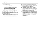
... at the left . Invalid EEPROM data. The graph does not operate with the best resolution. Error Messages Replace the battery immediately. Calibrate Meter. The bar graph also has a zoom function, as described under "Zoom Mode". Have Meter serviced. bAtt diSC EEPr Err CAL Err LEAd Feature 0L Indication The number of segments is in manual range mode. 12 Number R -- Invalid calibration data. In the capacitance function, too...
... at the left . Invalid EEPROM data. The graph does not operate with the best resolution. Error Messages Replace the battery immediately. Calibrate Meter. The bar graph also has a zoom function, as described under "Zoom Mode". Have Meter serviced. bAtt diSC EEPr Err CAL Err LEAd Feature 0L Indication The number of segments is in manual range mode. 12 Number R -- Invalid calibration data. In the capacitance function, too...

FE 83V & 87V Users Manual
Page 21
... to stop you by making a chirping sound and the display flashes "LEAd". If MIN MAX Recording is not set to mV. Input Alert Feature If a test lead is very low, so the Meter acts like a short circuit. Power-Up Options Holding a button down while turning the Meter on activates a power-up options. Table 4 includes the power-up option. Making Measurements W Caution Placing...
... to stop you by making a chirping sound and the display flashes "LEAd". If MIN MAX Recording is not set to mV. Input Alert Feature If a test lead is very low, so the Meter acts like a short circuit. Power-Up Options Holding a button down while turning the Meter on activates a power-up options. Table 4 includes the power-up option. Making Measurements W Caution Placing...

FE 83V & 87V Users Manual
Page 24
... V Users Manual Measuring Temperature (87) The Meter measures the temperature of these ranges show OL on or off. Connect a type-K thermocouple to enter temperature mode. 4. The continuity test features a beeper that sounds as long as shown in Figure 4. For temperatures out of that while the Meter is rated for continuity, set up the Meter as a circuit is no thermocouple connected, the display...
... V Users Manual Measuring Temperature (87) The Meter measures the temperature of these ranges show OL on or off. Connect a type-K thermocouple to enter temperature mode. 4. The continuity test features a beeper that sounds as long as shown in Figure 4. For temperatures out of that while the Meter is rated for continuity, set up the Meter as a circuit is no thermocouple connected, the display...
FE 83V & 87V Users Manual
Page 26
The Meter's resistance ranges are some tips for measuring resistance: • The measured value of error to apply a lower current in Figure...is suspected, press C to resistance measurements. If the value is higher, use the relative (REL) mode to conduct. The Meter measures resistance by sending a small current through all high-voltage capacitors before measuring...use the higher value. 80 Series V Users Manual Measuring Resistance WCaution To avoid possible damage to the Meter or to Table 18. 18 To measure resistance, set up the Meter as shown in the next higher range...
The Meter's resistance ranges are some tips for measuring resistance: • The measured value of error to apply a lower current in Figure...is suspected, press C to resistance measurements. If the value is higher, use the relative (REL) mode to conduct. The Meter measures resistance by sending a small current through all high-voltage capacitors before measuring...use the higher value. 80 Series V Users Manual Measuring Resistance WCaution To avoid possible damage to the Meter or to Table 18. 18 To measure resistance, set up the Meter as shown in the next higher range...

FE 83V & 87V Users Manual
Page 29
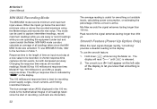
... Peak MIN MAX 4½ DIGITS 1 Second ˚C/˚F RANGE REL mV V AutoHOLD Hz % mA A LO V A OFF A mA A COM V 10A MAX FUSED 400mA FUSED + Figure 6. Measuring Capacitance aom10f.eps 21 To measure capacitance, set up the Meter as shown in Figure 6. ...use the relative (REL) mode to the equipment under test, disconnect circuit power and discharge all high-voltage capacitors before measuring capacitance. Use the dc voltage function to confirm that the capacitor is present on the capacitor being tested, the display shows "diSC". To improve the accuracy of the Meter...
... Peak MIN MAX 4½ DIGITS 1 Second ˚C/˚F RANGE REL mV V AutoHOLD Hz % mA A LO V A OFF A mA A COM V 10A MAX FUSED 400mA FUSED + Figure 6. Measuring Capacitance aom10f.eps 21 To measure capacitance, set up the Meter as shown in Figure 6. ...use the relative (REL) mode to the equipment under test, disconnect circuit power and discharge all high-voltage capacitors before measuring capacitance. Use the dc voltage function to confirm that the capacitor is present on the capacitor being tested, the display shows "diSC". To improve the accuracy of the Meter...

FE 83V & 87V Users Manual
Page 32
...The Meter's current ranges are sure the current is less than 400 mA continuously or less than 1000 V. Discharge all measurements. • Never place the probes across (in series with ) any circuit or component when the leads are plugged into the A terminal. 80 Series V Users Manual ...displayed as follows: 1. For currents between 6 mA and 400 mA, insert the red lead into the COM terminal. Turn off power to Figure 8 and proceed as an rms value. AC current is greater than 600 mA for all highvoltage capacitors. 2. Note To avoid blowing the Meter's 400 mA fuse, use...
...The Meter's current ranges are sure the current is less than 400 mA continuously or less than 1000 V. Discharge all measurements. • Never place the probes across (in series with ) any circuit or component when the leads are plugged into the A terminal. 80 Series V Users Manual ...displayed as follows: 1. For currents between 6 mA and 400 mA, insert the red lead into the COM terminal. Turn off power to Figure 8 and proceed as an rms value. AC current is greater than 600 mA for all highvoltage capacitors. 2. Note To avoid blowing the Meter's 400 mA fuse, use...

FE 83V & 87V Users Manual
Page 34
... the Meter's fuses as described under "Testing the Fuses". • A current Meter drops a small voltage across itself, which might affect circuit operation. If you are sure the Meter is 0 and you are using the values listed in the specifications in Table 14. 26 If you are using the A terminal, set the rotary switch to normal operation. touch the red probe to note the unit given...
... the Meter's fuses as described under "Testing the Fuses". • A current Meter drops a small voltage across itself, which might affect circuit operation. If you are sure the Meter is 0 and you are using the values listed in the specifications in Table 14. 26 If you are using the A terminal, set the rotary switch to normal operation. touch the red probe to note the unit given...

FE 83V & 87V Users Manual
Page 37
... V switching signals in multiple triggering. (Normally, a distortion-free signal can change the slope for measuring the on or off time of logic and switching signals. then scroll to measure frequency; then press Hz a second time. Measuring Duty Cycle Duty cycle (or duty factor) is the percentage of time a signal is unstable, press MIN MAX; For 5 V logic signals, use the 60 V dc range. The duty cycle mode...
... V switching signals in multiple triggering. (Normally, a distortion-free signal can change the slope for measuring the on or off time of logic and switching signals. then scroll to measure frequency; then press Hz a second time. Measuring Duty Cycle Duty cycle (or duty factor) is the percentage of time a signal is unstable, press MIN MAX; For 5 V logic signals, use the 60 V dc range. The duty cycle mode...

FE 83V & 87V Users Manual
Page 39
... continue with a maximum display of 10. For peak adjustments, set the Meter to set a new reference; The display reads zero. Readings are displayed at 10 times the normal resolution with the adjustment. Zoom Mode (Power Up Option Only) To use the Rel Zoom Bar Graph: 1. Hold down F while turning the Meter on the zoom bar graph is lit. If an overange symbol lights (< >), press F twice to...
... continue with a maximum display of 10. For peak adjustments, set the Meter to set a new reference; The display reads zero. Readings are displayed at 10 times the normal resolution with the adjustment. Zoom Mode (Power Up Option Only) To use the Rel Zoom Bar Graph: 1. Hold down F while turning the Meter on the zoom bar graph is lit. If an overange symbol lights (< >), press F twice to...
FE 83V & 87V Users Manual
Page 40
... use MIN MAX mode, refer to the functions in the 100 ms mode is the mathematical integral of the display to capture intermittent readings, record maximum readings while you are operating the equipment under test and cannot watch the Meter. 80 Series V Users Manual MIN MAX Recording Mode The MIN MAX mode records minimum and maximum input values. The 250 µs response time is released. 2. Changing...
... use MIN MAX mode, refer to the functions in the 100 ms mode is the mathematical integral of the display to capture intermittent readings, record maximum readings while you are operating the equipment under test and cannot watch the Meter. 80 Series V Users Manual MIN MAX Recording Mode The MIN MAX mode records minimum and maximum input values. The 250 µs response time is released. 2. Changing...

FE 83V & 87V Users Manual
Page 47
Table 8. Service and Parts Qty. 1 1 1 1 3 5 2 1 1 1 1 1 1 2 1 1 1 1 4 1 1 Fluke Part or Model Number 2139179 2064217 943121 803293 832246 448456 817460 2073906 2074025 2073992 2073871 2100482 822643 824466 828541 831933 2074033 2073938 1567683 2073950 2073945 39 Replacement Parts Item Description BT1 Battery, 9 V BT2 Cable Assy, 9 V Battery Snap F1 W Fuse, 0.440 A, 1000 V, FAST F2 W Fuse, 11 A, 1000 V, FAST H2-4 Screw, Case H5-9 Screw, Bottom Shield J1-2 Elastomeric Connector MP2 Shield...
Table 8. Service and Parts Qty. 1 1 1 1 3 5 2 1 1 1 1 1 1 2 1 1 1 1 4 1 1 Fluke Part or Model Number 2139179 2064217 943121 803293 832246 448456 817460 2073906 2074025 2073992 2073871 2100482 822643 824466 828541 831933 2074033 2073938 1567683 2073950 2073945 39 Replacement Parts Item Description BT1 Battery, 9 V BT2 Cable Assy, 9 V Battery Snap F1 W Fuse, 0.440 A, 1000 V, FAST F2 W Fuse, 11 A, 1000 V, FAST H2-4 Screw, Case H5-9 Screw, Bottom Shield J1-2 Elastomeric Connector MP2 Shield...

FE 83V & 87V Users Manual
Page 52
... Meter may produce a much larger constant error in later measurements. 3. Specification increases from 3 % to 3. 80 Series V Users Manual Detailed Specifications For all detailed specifications: Accuracy is given as ±([% of reading] + [number of least significant digits]) at 18° C to 28° C, with leads shorted, will cause only a 2-digit change for a period of one year after calibration. Model 87 AC Voltage Function Specifications Function Range...
... Meter may produce a much larger constant error in later measurements. 3. Specification increases from 3 % to 3. 80 Series V Users Manual Detailed Specifications For all detailed specifications: Accuracy is given as ±([% of reading] + [number of least significant digits]) at 18° C to 28° C, with leads shorted, will cause only a 2-digit change for a period of one year after calibration. Model 87 AC Voltage Function Specifications Function Range...

FE 83V & 87V Users Manual
Page 53
... of 200 counts, add 10 counts. 2. Model 83 AC Voltage Function Specifications Function Range Resolution K1 600.0 mV 0.1 mV 6.000 V 0.001 V 60.00 V 0.01 V 600.0 V 0.1 V 1000 V 1 V 1. Frequency range: 1 kHz to 2.5 kHz. 50 Hz - 60 Hz ± (0.5 % + 4) ± (0.5 % + 2) ± (0.5 % + 2) ± (0.5 % + 2) ± (0.5 % + 2) Accuracy 30 Hz - 1 kHz ± (1.0 % + 4) ± (1.0 % + 4) ± (1.0 % + 4) ± (1.0 % + 4) ± (1.0 % + 4) Specifications 1 kHz - 5 kHz ± (2.0 % + 4) ± (2.0 % + 4) ± (2.0 % + 4) ±...
... of 200 counts, add 10 counts. 2. Model 83 AC Voltage Function Specifications Function Range Resolution K1 600.0 mV 0.1 mV 6.000 V 0.001 V 60.00 V 0.01 V 600.0 V 0.1 V 1000 V 1 V 1. Frequency range: 1 kHz to 2.5 kHz. 50 Hz - 60 Hz ± (0.5 % + 4) ± (0.5 % + 2) ± (0.5 % + 2) ± (0.5 % + 2) ± (0.5 % + 2) Accuracy 30 Hz - 1 kHz ± (1.0 % + 4) ± (1.0 % + 4) ± (1.0 % + 4) ± (1.0 % + 4) ± (1.0 % + 4) Specifications 1 kHz - 5 kHz ± (2.0 % + 4) ± (2.0 % + 4) ± (2.0 % + 4) ±...

Getting Started Guide
Page 5
... iii Rotary Switch Positions...5 4. Pushbuttons ...6 5. Current Function Specifications 18 12. DC Voltage, Resistance, and Conductance Function Specifications 17 10. MIN MAX Recording Specifications 21 List of the Terminals 21 16. MIN MAX Functions...12 7. Model 87 AC Voltage Function Specifications 15 8. Temperature Specifications (87 Only 17 11. Frequency Counter Specifications 19 14. List of Tables Table Title Page 1. Electrical Symbols ...3 2. Inputs...4 3. Display Features...9 6. Model 83...
... iii Rotary Switch Positions...5 4. Pushbuttons ...6 5. Current Function Specifications 18 12. DC Voltage, Resistance, and Conductance Function Specifications 17 10. MIN MAX Recording Specifications 21 List of the Terminals 21 16. MIN MAX Functions...12 7. Model 87 AC Voltage Function Specifications 15 8. Temperature Specifications (87 Only 17 11. Frequency Counter Specifications 19 14. List of Tables Table Title Page 1. Electrical Symbols ...3 2. Inputs...4 3. Display Features...9 6. Model 83...

Getting Started Guide
Page 16
... Res) mode. bAtt diSC EEPr Err CAL Err LEAd F8/Err OPEn Display Messages Replace the battery immediately. Invalid EEPROM data. Calibrate Meter. Used for duty cycle measurements. e, Me, ke Ohm, Megohm, Kilohm Hz, kHz Hertz, Kilohertz AC DC Alternating current, direct current °C, °F Degrees Celsius, Degrees Fahrenheit 610000 mV Displays selected range HiRes The Meter is detected. For more information, See...
... Res) mode. bAtt diSC EEPr Err CAL Err LEAd F8/Err OPEn Display Messages Replace the battery immediately. Invalid EEPROM data. Calibrate Meter. Used for duty cycle measurements. e, Me, ke Ohm, Megohm, Kilohm Hz, kHz Hertz, Kilohertz AC DC Alternating current, direct current °C, °F Degrees Celsius, Degrees Fahrenheit 610000 mV Displays selected range HiRes The Meter is detected. For more information, See...

Getting Started Guide
Page 21
... a much larger constant error in later measurements. [3] Frequency range: 1 kHz to 2.5 kHz. [4] A residual reading of up to 13 digits with relative humidity up to 100 % of range. Model 87 is given as 45 - 65 Hz +1 % + 4 ± (1.0 % + 4) -6 % - 4[5] unspecified unspecified unspecified [1] Below 10 % of range, add 12 counts. [2] The Meter is in the 4 ½-digit mode, multiply the number of range. AC crest factor...
... a much larger constant error in later measurements. [3] Frequency range: 1 kHz to 2.5 kHz. [4] A residual reading of up to 13 digits with relative humidity up to 100 % of range. Model 87 is given as 45 - 65 Hz +1 % + 4 ± (1.0 % + 4) -6 % - 4[5] unspecified unspecified unspecified [1] Below 10 % of range, add 12 counts. [2] The Meter is in the 4 ½-digit mode, multiply the number of range. AC crest factor...

Getting Started Guide
Page 22
Model 83 AC Voltage Function Specifications Function Range Resolution Accuracy K1 600.0 mV 0.1 mV 6.000 V 0.001 V 60.00 V 0.01 V 600.0 V 0.1 V 1000 V 1 V 1. Frequency range: 1 kHz to 2.5 kHz. 50 Hz - 60 Hz ± (0.5 % + 4) ± (0.5 % + 2) ± (0.5 % + 2) ± (0.5 % + 2) ± (0.5 % + 2) 30 Hz - 1 kHz ± (1.0 % + 4) ± (1.0 % + 4) ± (1.0 % + 4) ± (1.0 % + 4) ± (1.0 % + 4) 1 kHz - 5 kHz ± (2.0 % + 4) ± (2.0 % + 4) ± (2.0 % + 4) ± (2.0 % + 4)2 unspecified 16 80 Series V Getting Started Manual Table 8. Below...
Model 83 AC Voltage Function Specifications Function Range Resolution Accuracy K1 600.0 mV 0.1 mV 6.000 V 0.001 V 60.00 V 0.01 V 600.0 V 0.1 V 1000 V 1 V 1. Frequency range: 1 kHz to 2.5 kHz. 50 Hz - 60 Hz ± (0.5 % + 4) ± (0.5 % + 2) ± (0.5 % + 2) ± (0.5 % + 2) ± (0.5 % + 2) 30 Hz - 1 kHz ± (1.0 % + 4) ± (1.0 % + 4) ± (1.0 % + 4) ± (1.0 % + 4) ± (1.0 % + 4) 1 kHz - 5 kHz ± (2.0 % + 4) ± (2.0 % + 4) ± (2.0 % + 4) ± (2.0 % + 4)2 unspecified 16 80 Series V Getting Started Manual Table 8. Below...


