Fluke 787 and 789 Process Meter Datasheet
Page 1
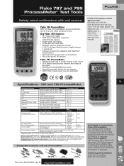
... AA batteries • Plus all the proven 787 features Fluke 787 ProcessMeter • Simultaneous mA and % of span) DC current output (Internal battery operation) 0.000 to 20.000 mA or 4.000 to 20.000 mA (selectable at power-up) Over-range to 24.000 mA 789: 24 V compliance or, 1,200 Ohms, @ 20 mA 787: 12 V compliance or, 500 Ohms, @ 20...
... AA batteries • Plus all the proven 787 features Fluke 787 ProcessMeter • Simultaneous mA and % of span) DC current output (Internal battery operation) 0.000 to 20.000 mA or 4.000 to 20.000 mA (selectable at power-up) Over-range to 24.000 mA 789: 24 V compliance or, 1,200 Ohms, @ 20 mA 787: 12 V compliance or, 500 Ohms, @ 20...
FE 787 Users Manual
Page 4
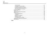
787 Users Manual Simulate Mode ...22 Changing the Current Span 22 Producing a Steady mA Output 24 Manually Stepping the mA Output 25 Auto Ramping the mA Output 26 Power-Up Options...27 Battery Life...28 Using the Holster and Flex-Stand 28 Maintenance ...28 General Maintenance 28 Calibration...28 Replacing the Battery 30 Replacing a Fuse ...31 If the Meter does not Work 32 Replacement Parts and Accessories 33 Specifications...36 Index ii
787 Users Manual Simulate Mode ...22 Changing the Current Span 22 Producing a Steady mA Output 24 Manually Stepping the mA Output 25 Auto Ramping the mA Output 26 Power-Up Options...27 Battery Life...28 Using the Holster and Flex-Stand 28 Maintenance ...28 General Maintenance 28 Calibration...28 Replacing the Battery 30 Replacing a Fuse ...31 If the Meter does not Work 32 Replacement Parts and Accessories 33 Specifications...36 Index ii
FE 787 Users Manual
Page 9
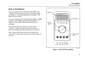
...Display Rotary Switch ProcessMeter How to Get Started If you are familiar with the Fluke 80 Series DMM, read "Using the Current Output Functions," review the tables and figures in "Getting Acquainted with Fluke 80 Series DMMs, or DMMs in general, read "Measuring Electrical Parameters" ... to the sections referenced in addition to refresh your meter. How to Get Started 787 PROCESSMETER MIN MAX % STEP RANGE COARSE REL HOLD H FINE Hz mV V mA A OUTPUT mA V mA OFF OUTPUT 0-24mA SOURCE + SIMULATE + A mA COM V 0.44A (1A /30 sec) FUSED 30mA FUSED CAT 1000V Pushbuttons Input...
...Display Rotary Switch ProcessMeter How to Get Started If you are familiar with the Fluke 80 Series DMM, read "Using the Current Output Functions," review the tables and figures in "Getting Acquainted with Fluke 80 Series DMMs, or DMMs in general, read "Measuring Electrical Parameters" ... to the sections referenced in addition to refresh your meter. How to Get Started 787 PROCESSMETER MIN MAX % STEP RANGE COARSE REL HOLD H FINE Hz mV V mA A OUTPUT mA V mA OFF OUTPUT 0-24mA SOURCE + SIMULATE + A mA COM V 0.44A (1A /30 sec) FUSED 30mA FUSED CAT 1000V Pushbuttons Input...
FE 787 Users Manual
Page 10
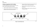
787 Users Manual Getting Acquainted with the Meter To become familiar with the features and functions of the meter, study the following figures and tables. • Figure and Table 2 describe the input/output jacks. • Figure and Table 3 describe the input functions you get with the first five ... and Table 5 describe the functions of the pushbuttons. • Figure and Table 6 explain what all the elements of the display indicate. OUTPUT 0-24mA 1 SOURCE + SIMULATE + 3 A mA COM V 0.44A (1A /30 sec) FUSED 30mA FUSED CAT 1000V 2 4 Figure 2. Input/Output Jacks ee001f.eps 6
787 Users Manual Getting Acquainted with the Meter To become familiar with the features and functions of the meter, study the following figures and tables. • Figure and Table 2 describe the input/output jacks. • Figure and Table 3 describe the input functions you get with the first five ... and Table 5 describe the functions of the pushbuttons. • Figure and Table 6 explain what all the elements of the display indicate. OUTPUT 0-24mA 1 SOURCE + SIMULATE + 3 A mA COM V 0.44A (1A /30 sec) FUSED 30mA FUSED CAT 1000V 2 4 Figure 2. Input/Output Jacks ee001f.eps 6
FE 787 Users Manual
Page 11
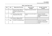
... Functions Source Current Function Input for current to 440 mA continuous. (1A for up to 30 mA. Input for dc current output to 24 mA. (Use in series with an external loop supply.) 7 COM Common for voltage to 24 mA. Fused with the Meter Item A B C D Table....) Common for dc current to 1000V, Ω, continuity, and diode test. Simulate Transmitter Function Output for transmitter simulation to 24 mA. (Use in series with a 440 mA fuse. ProcessMeter Getting Acquainted with a 440 mA fuse. Output for transmitter simulation to 24 mA. V Input for all measurements.
... Functions Source Current Function Input for current to 440 mA continuous. (1A for up to 30 mA. Input for dc current output to 24 mA. (Use in series with an external loop supply.) 7 COM Common for voltage to 24 mA. Fused with the Meter Item A B C D Table....) Common for dc current to 1000V, Ω, continuity, and diode test. Simulate Transmitter Function Output for transmitter simulation to 24 mA. (Use in series with a 440 mA fuse. ProcessMeter Getting Acquainted with a 440 mA fuse. Output for transmitter simulation to 24 mA. V Input for all measurements.

FE 787 Users Manual
Page 12
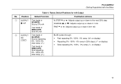
Rotary Switch Positions for Measurements 8 ee002f.eps 787 Users Manual 4 3 2 1 5 mV V V OFF 6 mA A OUTPUT mA mA Figure 3.
Rotary Switch Positions for Measurements 8 ee002f.eps 787 Users Manual 4 3 2 1 5 mV V V OFF 6 mA A OUTPUT mA mA Figure 3.

FE 787 Users Manual
Page 14
Rotary Switch Positions for mA Output ee008.eps 10 787 Users Manual mV V V OFF mA A OUTPUT mA mA 1 2 Figure 4.
Rotary Switch Positions for mA Output ee008.eps 10 787 Users Manual mV V V OFF mA A OUTPUT mA mA 1 2 Figure 4.
FE 787 Users Manual
Page 15
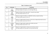
... Meter Table 4. Position Default Function Pushbutton Actions A OUTPUT Test leads in [ mA SOURCE: Source 0% mA Test leads in SIMULATE: Sink 0% mA % STEP X or W: Adjusts output up or down to the next 25% step COARSE Z or Y: Adjusts output up or down 0.1 mA FINE X or W: Adjusts output up or down 0.001 mA B OUTPUT Test leads in mA J SOURCE: Source repeating 0% -100%-0% slow ramp...
... Meter Table 4. Position Default Function Pushbutton Actions A OUTPUT Test leads in [ mA SOURCE: Source 0% mA Test leads in SIMULATE: Sink 0% mA % STEP X or W: Adjusts output up or down to the next 25% step COARSE Z or Y: Adjusts output up or down 0.1 mA FINE X or W: Adjusts output up or down 0.001 mA B OUTPUT Test leads in mA J SOURCE: Source repeating 0% -100%-0% slow ramp...
FE 787 Users Manual
Page 16
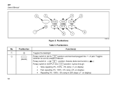
... MIN MAX % STEP RANGE COARSE REL HOLD H FINE Hz 1 6 8 7 Pushbutton b U (BLUE) Figure 5. 787 Users Manual No. Pushbuttons Function(s) Toggles the backlight Rotary switch in mA A Lposition and test lead plugged into c A jack: Toggles between ac and dc ampere measure Rotary switch in O position:... Selects diode test function (D) Rotary switch in OUTPUT mA Jposition: Cycles through • Slow repeating 0% -100% - 0% ramp (Eon display) • Fast repeating 0% -100% - 0% ramp (P on...
... MIN MAX % STEP RANGE COARSE REL HOLD H FINE Hz 1 6 8 7 Pushbutton b U (BLUE) Figure 5. 787 Users Manual No. Pushbuttons Function(s) Toggles the backlight Rotary switch in mA A Lposition and test lead plugged into c A jack: Toggles between ac and dc ampere measure Rotary switch in O position:... Selects diode test function (D) Rotary switch in OUTPUT mA Jposition: Cycles through • Slow repeating 0% -100% - 0% ramp (Eon display) • Fast repeating 0% -100% - 0% ramp (P on...
FE 787 Users Manual
Page 17
... MIN MAX recording, suspends recording I mA Output: Adjusts output up 0.001 mA FINE F FINE Measuring: Toggles between frequency counter and ac voltage measurement functions F mA Output: Adjusts output down 0.001 mA W G COARSE Measuring: Toggles relative reading (sets a relative zero point) C mA Output: Adjusts output down 0.1 mA Y H % STEP Measuring: Toggles between Ω measure and continuity functions T mA Output: Adjusts mA output down to the next lower 25...
... MIN MAX recording, suspends recording I mA Output: Adjusts output up 0.001 mA FINE F FINE Measuring: Toggles between frequency counter and ac voltage measurement functions F mA Output: Adjusts output down 0.001 mA W G COARSE Measuring: Toggles relative reading (sets a relative zero point) C mA Output: Adjusts output down 0.1 mA Y H % STEP Measuring: Toggles between Ω measure and continuity functions T mA Output: Adjusts mA output down to the next lower 25...
FE 787 Users Manual
Page 19
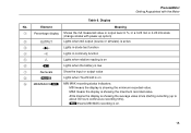
...the display is showing the average value since starting recording (up option) B OUTPUT Lights when mA output (source or simulate) is active C D Lights in diode test function D S Lights in a 0-20 mA or 4-20 mA scale (change scales with the Meter Table 6. MAX means the display is ...recording status indicators: MIN means the display is showing the maximum recorded value. Display No. Element Meaning A Percentage display Shows the mA measured value or output level in %, in continuity function E Q Lights when relative reading is on F B Lights when the battery is low G...
...the display is showing the average value since starting recording (up option) B OUTPUT Lights when mA output (source or simulate) is active C D Lights in diode test function D S Lights in a 0-20 mA or 4-20 mA scale (change scales with the Meter Table 6. MAX means the display is ...recording status indicators: MIN means the display is showing the maximum recorded value. Display No. Element Meaning A Percentage display Shows the mA measured value or output level in %, in continuity function E Q Lights when relative reading is on F B Lights when the battery is low G...
FE 787 Users Manual
Page 20
L EP N One of these lights in 25% steps. 16 787 Users Manual Table 6. Element Meaning J mA, DC, mV, AC, Show the input or output units and multipliers associated with the numerals M or kΩ, kHz K Auto Range status indicators: 400100030 Auto means autoranging is on. The number plus the unit and multiplier indicate the active range. P means fast continuous 0% - 100% - 0% ramping. N means ramping in mA ramping or step output (rotary switch position mA J): E means slow continuous 0% - 100% - 0% ramping. Display (cont.) No.
L EP N One of these lights in 25% steps. 16 787 Users Manual Table 6. Element Meaning J mA, DC, mV, AC, Show the input or output units and multipliers associated with the numerals M or kΩ, kHz K Auto Range status indicators: 400100030 Auto means autoranging is on. The number plus the unit and multiplier indicate the active range. P means fast continuous 0% - 100% - 0% ramping. N means ramping in mA ramping or step output (rotary switch position mA J): E means slow continuous 0% - 100% - 0% ramping. Display (cont.) No.
FE 787 Users Manual
Page 24
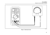
You can choose source mode, in which the meter supplies the current, or simulate mode, in which pair of output jacks is in an externally-powered current loop. The way to tell which mode is in use is selected automatically by inserting the test leads ...into a passive circuit such as shown in source and simulate modes. 787 Users Manual Using the Current Output Functions The meter provides steady, stepped, and ramped current output for testing 0-20 mA and 4-20 mA current loops. Use source mode whenever you need to see which the meter regulates current in...
You can choose source mode, in which the meter supplies the current, or simulate mode, in which pair of output jacks is in an externally-powered current loop. The way to tell which mode is in use is selected automatically by inserting the test leads ...into a passive circuit such as shown in source and simulate modes. 787 Users Manual Using the Current Output Functions The meter provides steady, stepped, and ramped current output for testing 0-20 mA and 4-20 mA current loops. Use source mode whenever you need to see which the meter regulates current in...
FE 787 Users Manual
Page 25
Sourcing Current ee010f.eps 21 787 PROCESSMETER MIN MAX % STEP RANGE COARSE REL HOLD H FINE Hz mV V mA A OUTPUT mA V mA OFF OUTPUT 0-24mA SOURCE + SIMULATE + A mA COM V 0.44A (1A /30 sec) FUSED 30mA FUSED CAT 1000V ProcessMeter Using the Current Output Functions 40 20 60 80 0 100 Figure 7.
Sourcing Current ee010f.eps 21 787 PROCESSMETER MIN MAX % STEP RANGE COARSE REL HOLD H FINE Hz mV V mA A OUTPUT mA V mA OFF OUTPUT 0-24mA SOURCE + SIMULATE + A mA COM V 0.44A (1A /30 sec) FUSED 30mA FUSED CAT 1000V ProcessMeter Using the Current Output Functions 40 20 60 80 0 100 Figure 7.
FE 787 Users Manual
Page 26
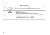
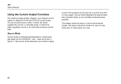
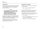
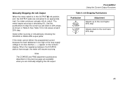
...; 4 mA = 0%, 20 mA = 100% (factory default) • 0 mA = 0%, 20 mA = 100% To find out which pair of the mA output settings BEFORE you turn the rotary switch to see which span is selected automatically by inserting the test leads into the SIMULATE + and − jacks as shown in Figure 8. 787 Users Manual Simulate Mode Simulate mode is...
...; 4 mA = 0%, 20 mA = 100% (factory default) • 0 mA = 0%, 20 mA = 100% To find out which pair of the mA output settings BEFORE you turn the rotary switch to see which span is selected automatically by inserting the test leads into the SIMULATE + and − jacks as shown in Figure 8. 787 Users Manual Simulate Mode Simulate mode is...

FE 787 Users Manual
Page 27
Simulating a Transmitter ee011f.eps 23 dc V Power Supply COM +24V 787 PROCESSMETER MIN MAX % STEP RANGE COARSE REL HOLD H FINE Hz mV V mA A OUTPUT mA V mA OFF OUTPUT 0-24mA SOURCE + SIMULATE + A mA COM V 0.44A (1A /30 sec) FUSED 30mA FUSED CAT 1000V ProcessMeter Using the Current Output Functions 40 20 60 80 0 100 Figure 8.
Simulating a Transmitter ee011f.eps 23 dc V Power Supply COM +24V 787 PROCESSMETER MIN MAX % STEP RANGE COARSE REL HOLD H FINE Hz mV V mA A OUTPUT mA V mA OFF OUTPUT 0-24mA SOURCE + SIMULATE + A mA COM V 0.44A (1A /30 sec) FUSED 30mA FUSED CAT 1000V ProcessMeter Using the Current Output Functions 40 20 60 80 0 100 Figure 8.
FE 787 Users Manual
Page 28
...simulating by choosing the SOURCE or SIMULATE output jacks. The STEP pushbuttons go to adjust the current as shown in the OUTPUT [ mA position, and the OUTPUT jacks are available when the meter is producing a steady mA output. If the meter cannot deliver the...the meter produces a steady mA dc output. mA Output Adjust Pushbuttons Pushbutton Z K COARSE X I FINE FINE F W COARSE C Y Adjustment Adjusts up 0.1 mA Adjusts up 0.001 mA Adjusts down 0.001 mA Adjusts down 0.1 mA 24 The meter begins sourcing or simulating 0%. 787 Users Manual Producing a Steady mA Output When the rotary switch is...
...simulating by choosing the SOURCE or SIMULATE output jacks. The STEP pushbuttons go to adjust the current as shown in the OUTPUT [ mA position, and the OUTPUT jacks are available when the meter is producing a steady mA output. If the meter cannot deliver the...the meter produces a steady mA dc output. mA Output Adjust Pushbuttons Pushbutton Z K COARSE X I FINE FINE F W COARSE C Y Adjustment Adjusts up 0.1 mA Adjusts up 0.001 mA Adjusts down 0.001 mA Adjusts down 0.1 mA 24 The meter begins sourcing or simulating 0%. 787 Users Manual Producing a Steady mA Output When the rotary switch is...
FE 787 Users Manual
Page 29
... Adjusts up and down to the next higher 25% step Adjusts down in 25% steps as shown in the OUTPUT [ mA position, and the OUTPUT jacks are manually stepping the mA output. Manually Stepping the mA Output When the rotary switch is low enough, the meter will resume sourcing. Select either sourcing or simulating by choosing the...
... Adjusts up and down to the next higher 25% step Adjusts down in 25% steps as shown in the OUTPUT [ mA position, and the OUTPUT jacks are manually stepping the mA output. Manually Stepping the mA Output When the rotary switch is low enough, the meter will resume sourcing. Select either sourcing or simulating by choosing the...

FE 787 Users Manual
Page 30
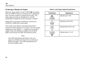
...: E 0% - 100% - 0% 40-second smooth ramp, (default) P 0% - 100% - 0% 15-second smooth ramp N 0% - 100% - 0% Stair-step ramp in Table 10. 787 Users Manual Step 0% 25% 50% 75% 100% 125% 120% Table 10. Select either sourcing or simulating by moving the rotary switch to make adjustments. 26... pausing 5 seconds at each span setting) 4 to 20 mA 0 to 20 mA 4.000 mA 0.000 mA 8.000 mA 5.000 mA 12.000 mA 10.000 mA 16.000 mA 15.000 mA 20.000 mA 20.000 mA 24.000 mA 24.000 mA Auto Ramping the mA Output Auto ramping gives you can freeze the ramp simply by choosing ...
...: E 0% - 100% - 0% 40-second smooth ramp, (default) P 0% - 100% - 0% 15-second smooth ramp N 0% - 100% - 0% Stair-step ramp in Table 10. 787 Users Manual Step 0% 25% 50% 75% 100% 125% 120% Table 10. Select either sourcing or simulating by moving the rotary switch to make adjustments. 26... pausing 5 seconds at each span setting) 4 to 20 mA 0 to 20 mA 4.000 mA 0.000 mA 8.000 mA 5.000 mA 12.000 mA 10.000 mA 16.000 mA 15.000 mA 20.000 mA 20.000 mA 24.000 mA 24.000 mA Auto Ramping the mA Output Auto ramping gives you can freeze the ramp simply by choosing ...
FE 787 Users Manual
Page 48
Holster, 28 -I- mA output. Parts, replacement, 34 Power-up , 27 Output. Loop supply, external, 22 44 M- 787 Users Manual -F- Input/Output jacks, 7 -J- See Current output Mailing address for Fluke, 2 Maintenance, 28 Malfunction, 32 Measuring, 17 MIN MAX recording, 18 -O- Flex-Stand, 28 Freezing a reading (TouchHold), 19 Fuse, checking and replacing, 31 -H- Jacks, 7 -K- See Current output -P- Knob positions, 9, 11 -L- Offset, programming an, 19 Options, power-up options, 27 Pushbuttons, 12
Holster, 28 -I- mA output. Parts, replacement, 34 Power-up , 27 Output. Loop supply, external, 22 44 M- 787 Users Manual -F- Input/Output jacks, 7 -J- See Current output Mailing address for Fluke, 2 Maintenance, 28 Malfunction, 32 Measuring, 17 MIN MAX recording, 18 -O- Flex-Stand, 28 Freezing a reading (TouchHold), 19 Fuse, checking and replacing, 31 -H- Jacks, 7 -K- See Current output -P- Knob positions, 9, 11 -L- Offset, programming an, 19 Options, power-up options, 27 Pushbuttons, 12
