
Fluke 381 Users Manual
Page 1
All rights reserved. Specifications are trademarks of their respective companies. All product names are subject to change without notice. 381 Remote Display True-rms Clamp Meter Users Manual PN 3538357 July 2010 © 2010 Fluke Corporation. Printed in China.
All rights reserved. Specifications are trademarks of their respective companies. All product names are subject to change without notice. 381 Remote Display True-rms Clamp Meter Users Manual PN 3538357 July 2010 © 2010 Fluke Corporation. Printed in China.
Fluke 381 Users Manual
Page 4
381 Users Manual Display...17 Measurements...19 AC and DC Current (Jaw 19 AC Current (Flexible Current Probe 22 AC and DC Voltage 23 Resistance/Continuity 26 Inrush Current Measurement (Jaw and Flexible Current Probe 26 Frequency Measurement (Jaw and Flexible Current Probe 28 Maintenance...28 Cleaning the Meter and Flexible Current Probe 28 Battery Replacement 29 User-Replaceable Parts 31 Specifications ...32 Electrical Specifications 32 Mechanical Specifications 37 Environmental Specifications 38 ii
381 Users Manual Display...17 Measurements...19 AC and DC Current (Jaw 19 AC Current (Flexible Current Probe 22 AC and DC Voltage 23 Resistance/Continuity 26 Inrush Current Measurement (Jaw and Flexible Current Probe 26 Frequency Measurement (Jaw and Flexible Current Probe 28 Maintenance...28 Cleaning the Meter and Flexible Current Probe 28 Battery Replacement 29 User-Replaceable Parts 31 Specifications ...32 Electrical Specifications 32 Mechanical Specifications 37 Environmental Specifications 38 ii
Fluke 381 Users Manual
Page 6
...battery door is opened. 2 A Caution identifies conditions and procedures that pose hazard(s) to the user; Look for cracks or missing plastic. Symbols used on the Meter and in this manual or the protection provided by the Meter can be compromised. • Examine the case before the... you use the Meter. To register your product, visit http://register.fluke.com. Carefully look at www.fluke.com. 381 Users Manual • Singapore: +65-738-5655 • Anywhere in the world: +1-425-446-5500 Or, visit Fluke's website at the insulation around the connectors. • Never measure ...
...battery door is opened. 2 A Caution identifies conditions and procedures that pose hazard(s) to the user; Look for cracks or missing plastic. Symbols used on the Meter and in this manual or the protection provided by the Meter can be compromised. • Examine the case before the... you use the Meter. To register your product, visit http://register.fluke.com. Carefully look at www.fluke.com. 381 Users Manual • Singapore: +65-738-5655 • Anywhere in the world: +1-425-446-5500 Or, visit Fluke's website at the insulation around the connectors. • Never measure ...
Fluke 381 Users Manual
Page 8
... shock. • Adhere to prevent shock and arc blast injury where hazardous live conductors are exposed. • When measuring, keep fingers behind the Tactile Barrier. 381 Users Manual • Use extreme caution when working around or remove from HAZARDOUS LIVE conductors. • Take special care during fitting and removal of the Flexible Current...
... shock. • Adhere to prevent shock and arc blast injury where hazardous live conductors are exposed. • When measuring, keep fingers behind the Tactile Barrier. 381 Users Manual • Use extreme caution when working around or remove from HAZARDOUS LIVE conductors. • Take special care during fitting and removal of the Flexible Current...
Fluke 381 Users Manual
Page 10
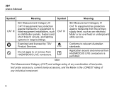
... an electricity Meter or an overhead or underground utility service. ® Examined and licensed by TÜV Product Services. ; Do not apply to relevant Australian standards. - 381 Users Manual Symbol Meaning Symbol Meaning CAT III IEC Measurement Category III CAT III equipment has protection against transients from HAZARDOUS LIVE conductors is the LOWEST rating...
... an electricity Meter or an overhead or underground utility service. ® Examined and licensed by TÜV Product Services. ; Do not apply to relevant Australian standards. - 381 Users Manual Symbol Meaning Symbol Meaning CAT III IEC Measurement Category III CAT III equipment has protection against transients from HAZARDOUS LIVE conductors is the LOWEST rating...
Fluke 381 Users Manual
Page 12
... to let the display module operate in detail. Features The following sections explain the Meter features in a different location than the Meter base. 381 Users Manual off and on, the user is encouraged to try to a Meter base at the same time. 8 Different display modules can be on . The term "IC:" before the radio...
... to let the display module operate in detail. Features The following sections explain the Meter features in a different location than the Meter base. 381 Users Manual off and on, the user is encouraged to try to a Meter base at the same time. 8 Different display modules can be on . The term "IC:" before the radio...
Fluke 381 Users Manual
Page 14
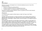
... complex waveforms. The flexible and lightweight measuring head allows quick and easy installation in hard-to tell you a hazardous voltage is at the Meter input. 381 Users Manual Hazardous Voltage Indicator When the Meter senses a voltage ±30 V or a voltage overload (OL), Y is shown on the display and the red high-voltage LED...
... complex waveforms. The flexible and lightweight measuring head allows quick and easy installation in hard-to tell you a hazardous voltage is at the Meter input. 381 Users Manual Hazardous Voltage Indicator When the Meter senses a voltage ±30 V or a voltage overload (OL), Y is shown on the display and the red high-voltage LED...
Fluke 381 Users Manual
Page 16
... capture this surge current reading. When Q is first powered on the Meter base will affect the readings. Measurements are one example of such an event. 381 Users Manual Inrush Inrush Current is surge current that occurs when an electrical device is displayed, the batteries for the removable display should be changed . Low Battery...
... capture this surge current reading. When Q is first powered on the Meter base will affect the readings. Measurements are one example of such an event. 381 Users Manual Inrush Inrush Current is surge current that occurs when an electrical device is displayed, the batteries for the removable display should be changed . Low Battery...
Fluke 381 Users Manual
Page 18
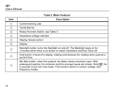
... display reading and releases the reading when pushed a second time. Hold L for 2 minutes when there is no button or switch interaction and then shuts off . 381 Users Manual Item A B C D E F G H I Table 2. Hazardous-voltage indicator Display release button Display Backlight button: turns the Backlight on for 2 seconds to exit min max mode. The Backlight stays...
... display reading and releases the reading when pushed a second time. Hold L for 2 minutes when there is no button or switch interaction and then shuts off . 381 Users Manual Item A B C D E F G H I Table 2. Hazardous-voltage indicator Display release button Display Backlight button: turns the Backlight on for 2 seconds to exit min max mode. The Backlight stays...
Fluke 381 Users Manual
Page 20
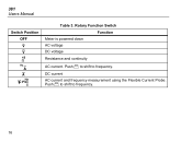
381 Users Manual Switch Position OFF K L K A C D Table 3. DC current AC current and frequency measurement using the Flexible Current Probe. Push Z to shift to frequency. 16 Push Z to shift to frequency. Rotary Function Switch Meter is powered down AC voltage DC voltage Function Resistance and continuity AC current.
381 Users Manual Switch Position OFF K L K A C D Table 3. DC current AC current and frequency measurement using the Flexible Current Probe. Push Z to shift to frequency. 16 Push Z to shift to frequency. Rotary Function Switch Meter is powered down AC voltage DC voltage Function Resistance and continuity AC current.
Fluke 381 Users Manual
Page 22
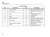
RF signal is being sent to remote display. Min, Max, or Avg reading is being shown. Min Max mode is taken at the Flexible Current Probe. Display Description Item Inrush is active H Hold is active I C Volts J D Amps K E Ohms, DC, AC, Hz L F Main display M G Remote display low-battery symbol N O Description Meter base low-battery symbol Measurement is active. 18 Measurement is present. 381 Users Manual Item A B Table 4. Continuity Hazardous voltage is taken at the Jaw.
RF signal is being sent to remote display. Min, Max, or Avg reading is being shown. Min Max mode is taken at the Flexible Current Probe. Display Description Item Inrush is active H Hold is active I C Volts J D Amps K E Ohms, DC, AC, Hz L F Main display M G Remote display low-battery symbol N O Description Meter base low-battery symbol Measurement is active. 18 Measurement is present. 381 Users Manual Item A B Table 4. Continuity Hazardous voltage is taken at the Jaw.
Fluke 381 Users Manual
Page 24
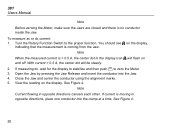
... no conductor inside the Jaw. Turn the Rotary Function Switch to zero the Meter. 3. Close the Jaw and center the conductor using the alignment marks. 5. 381 Users Manual Note Before zeroing the Meter, make sure the Jaws are closed and there is < 0.5 A, the center dot in the display icon X will be steady. 2. To...
... no conductor inside the Jaw. Turn the Rotary Function Switch to zero the Meter. 3. Close the Jaw and center the conductor using the alignment marks. 5. 381 Users Manual Note Before zeroing the Meter, make sure the Jaws are closed and there is < 0.5 A, the center dot in the display icon X will be steady. 2. To...
Fluke 381 Users Manual
Page 26
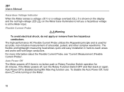
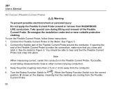
... Current Probe around or remove from the conductor. De-energize the installation under test or wear suitable protective clothing. Connect the Flexible Current Probe to . 381 Users Manual AC Current (Flexible Current Probe) XW Warning To prevent possible electrical shock or personal injury: Do not apply the Flexible Current Probe around the conductor...
... Current Probe around or remove from the conductor. De-energize the installation under test or wear suitable protective clothing. Connect the Flexible Current Probe to . 381 Users Manual AC Current (Flexible Current Probe) XW Warning To prevent possible electrical shock or personal injury: Do not apply the Flexible Current Probe around the conductor...
Fluke 381 Users Manual
Page 28
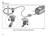
Flexible Current Probe Connection ghn09.eps 24 381 Users Manual 2 1 Figure 5.
Flexible Current Probe Connection ghn09.eps 24 381 Users Manual 2 1 Figure 5.
Fluke 381 Users Manual
Page 30
... as a motor or light ballast. With the device under test. Turn on the Meter display. Push E on the display. View the reading on the Meter. 4. 381 Users Manual Resistance/Continuity To measure resistance or continuity: 1. Remove power from the circuit being used for the measurement. 2. If the resistance is < 30 Ω, continuity is...
... as a motor or light ballast. With the device under test. Turn on the Meter display. Push E on the display. View the reading on the Meter. 4. 381 Users Manual Resistance/Continuity To measure resistance or continuity: 1. Remove power from the circuit being used for the measurement. 2. If the resistance is < 30 Ω, continuity is...
Fluke 381 Users Manual
Page 32
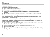
Cleaning the Meter and Flexible Current Probe XW Warning To avoid electrical shock, remove any input signals before cleaning. 381 Users Manual Frequency Measurement (Jaw and Flexible Current Probe) To measure frequency: 1. Center the Jaw or Flexible Current Probe around the measurement source. 3. ... Meter. Clean the instrument case with the plastics used for cleaning. Push Z on the Meter display. Do not immerse the Meter in this manual should be performed only by qualified personnel. Turn the Meter Rotary Function Switch to Hz. W Caution To avoid damaging the Meter, do not...
Cleaning the Meter and Flexible Current Probe XW Warning To avoid electrical shock, remove any input signals before cleaning. 381 Users Manual Frequency Measurement (Jaw and Flexible Current Probe) To measure frequency: 1. Center the Jaw or Flexible Current Probe around the measurement source. 3. ... Meter. Clean the instrument case with the plastics used for cleaning. Push Z on the Meter display. Do not immerse the Meter in this manual should be performed only by qualified personnel. Turn the Meter Rotary Function Switch to Hz. W Caution To avoid damaging the Meter, do not...
Fluke 381 Users Manual
Page 34
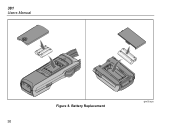
381 Users Manual Figure 8. Battery Replacement ghn03.eps 30
381 Users Manual Figure 8. Battery Replacement ghn03.eps 30
Fluke 381 Users Manual
Page 35
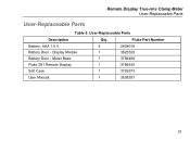
Fluke Part Number Battery, AAA 1.5 V 5 2838018 Battery Door - Display Module 1 3625529 Battery Door - User-Replaceable Parts Description Qty. Remote Display True-rms Clamp Meter User-Replaceable Parts User-Replaceable Parts Table 5. Meter Base 1 3766406 Fluke 381 Remote Display 1 3766445 Soft Case 1 3752973 User Manual 1 3538357 31
Fluke Part Number Battery, AAA 1.5 V 5 2838018 Battery Door - Display Module 1 3625529 Battery Door - User-Replaceable Parts Description Qty. Remote Display True-rms Clamp Meter User-Replaceable Parts User-Replaceable Parts Table 5. Meter Base 1 3766406 Fluke 381 Remote Display 1 3766445 Soft Case 1 3752973 User Manual 1 3538357 31
Fluke 381 Users Manual
Page 36
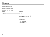
381 Users Manual Specifications Electrical Specifications AC Current Via Jaw Range 999.9 A Resolution 0.1 A Accuracy 2 % ± 5 digits (10-100 Hz) 5 % ± 5 digits (100-500 Hz) Crest Factor (50/60 Hz 3 @ 500 A 2.5 @ 600 A 1.42 @1000 A Add 2 % for C.F. > 2 32
381 Users Manual Specifications Electrical Specifications AC Current Via Jaw Range 999.9 A Resolution 0.1 A Accuracy 2 % ± 5 digits (10-100 Hz) 5 % ± 5 digits (100-500 Hz) Crest Factor (50/60 Hz 3 @ 500 A 2.5 @ 600 A 1.42 @1000 A Add 2 % for C.F. > 2 32

Fluke 381 Users Manual
Page 38
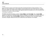
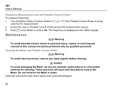
381 Users Manual Position Sensitivity A B C Figure 9. Position Sensitivity ghn12.eps 34
381 Users Manual Position Sensitivity A B C Figure 9. Position Sensitivity ghn12.eps 34


