Fluke 1550B MegOhmMeter Datasheet
Page 1
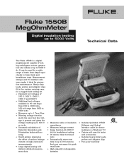
... to 1000 volts, 100 volt steps from simple spot checks to timed tests and breakdown tests. Heavy-duty leads, probes and alligator clips fit in up to 99 locations that user can be used for a wide range of tests: from 1000 to 5000 volts • Measures up to 1 Tera...to 5000 V dc. Measurement storage and PC interface soft- age is a digital megohmmeter capable of test- ing switchgear, motors, genera- Fluke 1550B MegOhmMeter Digital insulation testing up to 5000 Volts Technical Data The Fluke 1550B is present and gives the voltage reading up to 600 V ac or dc • Automatic ...
... to 1000 volts, 100 volt steps from simple spot checks to timed tests and breakdown tests. Heavy-duty leads, probes and alligator clips fit in up to 99 locations that user can be used for a wide range of tests: from 1000 to 5000 volts • Measures up to 1 Tera...to 5000 V dc. Measurement storage and PC interface soft- age is a digital megohmmeter capable of test- ing switchgear, motors, genera- Fluke 1550B MegOhmMeter Digital insulation testing up to 5000 Volts Technical Data The Fluke 1550B is present and gives the voltage reading up to 600 V ac or dc • Automatic ...
Fluke 1550B MegOhmMeter Datasheet
Page 2
... info@oFFparoxtmim(9o0ut5hm)er8e9cno0eu-n6rgt8r6iye6.sc+o1m(425) 446-5500 or www.MFayxF+l1uk(4e2S5)to4r4e6.-c5o11m6 Web access: http://www.fluke.com/ ©2003 Fluke Corporation. For operating temperatures outside the range (-20 °C to 0 °C and 35 °C to 50 °C), add +/- .25 % per... world up and running Windows® 95, 98, Me, 2000, NT4.0 Two-year warranty Included accessories Test leads and low leakage probes Alligator clips Interface adapter and cable Quicklink 1550B PC software Line cord Soft carrying case with waterproof bottom User's manual CD with battery) 170 mm x ...
... info@oFFparoxtmim(9o0ut5hm)er8e9cno0eu-n6rgt8r6iye6.sc+o1m(425) 446-5500 or www.MFayxF+l1uk(4e2S5)to4r4e6.-c5o11m6 Web access: http://www.fluke.com/ ©2003 Fluke Corporation. For operating temperatures outside the range (-20 °C to 0 °C and 35 °C to 50 °C), add +/- .25 % per... world up and running Windows® 95, 98, Me, 2000, NT4.0 Two-year warranty Included accessories Test leads and low leakage probes Alligator clips Interface adapter and cable Quicklink 1550B PC software Line cord Soft carrying case with waterproof bottom User's manual CD with battery) 170 mm x ...
FE 1550B Users Manual
Page 7
... of inactivity ⇒ Infrared (IR) port for downloading test data ⇒ PC software supplied The Meter meets EN 61557 Parts 1 and 2; Register your Meter at : www.fluke.com. 1550B MegOhmMeter Introduction The Fluke 1550B MegOhmMeter (hereafter "the Meter") is designed to protect against... CAT III equipment is a high voltage insulation tester for test results with user settable ID tag ⇒ Breakdown voltage indication ⇒ Rechargeable lead-acid battery ⇒ Auto shutoff after 30 minutes of the nearest Fluke distributor or Service Center, call: 1-888-99FLUKE (1-888-993...
... of inactivity ⇒ Infrared (IR) port for downloading test data ⇒ PC software supplied The Meter meets EN 61557 Parts 1 and 2; Register your Meter at : www.fluke.com. 1550B MegOhmMeter Introduction The Fluke 1550B MegOhmMeter (hereafter "the Meter") is designed to protect against... CAT III equipment is a high voltage insulation tester for test results with user settable ID tag ⇒ Breakdown voltage indication ⇒ Rechargeable lead-acid battery ⇒ Auto shutoff after 30 minutes of the nearest Fluke distributor or Service Center, call: 1-888-99FLUKE (1-888-993...
FE 1550B Users Manual
Page 8
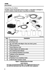
...test leads. The supplied test leads are for use with the items shown in Figure 1. If the Meter is damaged or an item is missing, contact the place of purchase immediately. 1 2 3 5 7 4 6 8 11 12 9 10 ASW01F.EPS Item Description A English Manual B AC Power Cord C X Test... Cables with Alligator Clips (red, black, green) D Soft Carrying Case E Quick Reference Card F Infrared Adapter with this instrument only. 1550B Users Manual Unpacking the Meter The Meter comes with other equipment 2 Do not ...
...test leads. The supplied test leads are for use with the items shown in Figure 1. If the Meter is damaged or an item is missing, contact the place of purchase immediately. 1 2 3 5 7 4 6 8 11 12 9 10 ASW01F.EPS Item Description A English Manual B AC Power Cord C X Test... Cables with Alligator Clips (red, black, green) D Soft Carrying Case E Quick Reference Card F Infrared Adapter with this instrument only. 1550B Users Manual Unpacking the Meter The Meter comes with other equipment 2 Do not ...
FE 1550B Users Manual
Page 9
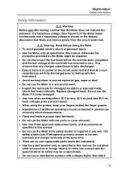
...allow other accessories or foreign objects to testing with this manual. Otherwise the protection provided by the Meter might be compromised. • Do not use the Meter in any parts or cover removed. • Use only Fluke approved replacement parts, and accessories as ... may be impaired. • Do not disconnect the test leads before the test has been completed and the test voltage at the same time. • There are no power to the circuit under test. Replace damaged leads. Check test lead continuity. MegOhmMeter Safety Information Safety Information XW Warning Before and...
...allow other accessories or foreign objects to testing with this manual. Otherwise the protection provided by the Meter might be compromised. • Do not use the Meter in any parts or cover removed. • Use only Fluke approved replacement parts, and accessories as ... may be impaired. • Do not disconnect the test leads before the test has been completed and the test voltage at the same time. • There are no power to the circuit under test. Replace damaged leads. Check test lead continuity. MegOhmMeter Safety Information Safety Information XW Warning Before and...
FE 1550B Users Manual
Page 12
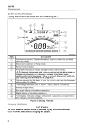
... Meter beeps continuously and a hazardous voltage is present at the test terminals. Digital display of insulation resistance. 1550B Users Manual Understanding the Display Display annunciators are shown and described in Ramp mode. XW Warning: Before and after testing, confirm that is present, disconnect test leads and remove power from the Meter before charging the battery...
... Meter beeps continuously and a hazardous voltage is present at the test terminals. Digital display of insulation resistance. 1550B Users Manual Understanding the Display Display annunciators are shown and described in Ramp mode. XW Warning: Before and after testing, confirm that is present, disconnect test leads and remove power from the Meter before charging the battery...
FE 1550B Users Manual
Page 13
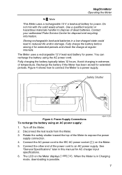
...and check the charge at regular intervals. Turn off the Meter. 2. Disconnect the test leads from the Meter. 3. MegOhmMeter Operating the Meter = Pb Note This Meter uses a rechargeable 12 V a lead-acid battery for power. Connect the other end of the power cord to the...expose the power supply connection. 4. Safety Shutter Figure 4. See "General Specifications" later in extremes of dead batteries. Contact your authorized Fluke Service Center for AC charger input specifications. 6. Avoid charging in this manual for disposal and recycling information. Figure 4 shows how to...
...and check the charge at regular intervals. Turn off the Meter. 2. Disconnect the test leads from the Meter. 3. MegOhmMeter Operating the Meter = Pb Note This Meter uses a rechargeable 12 V a lead-acid battery for power. Connect the other end of the power cord to the...expose the power supply connection. 4. Safety Shutter Figure 4. See "General Specifications" later in extremes of dead batteries. Contact your authorized Fluke Service Center for AC charger input specifications. 6. Avoid charging in this manual for disposal and recycling information. Figure 4 shows how to...
FE 1550B Users Manual
Page 14
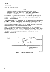
...end of the cable. The Guard (G) terminal is measured between the + and − output connections. 1550B Users Manual Using the Guard Terminal Note Insulation resistance is left unconnected. The Guard terminal is at the ... Figure 5 shows how to measure the resistance from degrading the accuracy of the conductors to the circuit under test. In this case, there is not in the measurement path. Surface Leakage Current ASW13F.EPS 8 When measuring... one of the insulation resistance measurement. For most tests, only two test leads are used to read a lower resistance than it should.
...end of the cable. The Guard (G) terminal is measured between the + and − output connections. 1550B Users Manual Using the Guard Terminal Note Insulation resistance is left unconnected. The Guard terminal is at the ... Figure 5 shows how to measure the resistance from degrading the accuracy of the conductors to the circuit under test. In this case, there is not in the measurement path. Surface Leakage Current ASW13F.EPS 8 When measuring... one of the insulation resistance measurement. For most tests, only two test leads are used to read a lower resistance than it should.

FE 1550B Users Manual
Page 15
... between the selected conductor and the outer shield, but eliminates the leakage path between the positive and negative terminals, and improves the accuracy of the test readings. Shield ( ) Leakage Current Figure 7. MegOhmMeter Operating the Meter Figure 6 shows how to prevent surface current leakage by connecting the Guard terminal to the unused... current is directed to a conductor wrapped around the inner insulation. Guard Terminal Connection ASW14F.EPS Figure 7 shows how to improve the measurement setup by connecting a lead from the measurement path between conductors.
... between the selected conductor and the outer shield, but eliminates the leakage path between the positive and negative terminals, and improves the accuracy of the test readings. Shield ( ) Leakage Current Figure 7. MegOhmMeter Operating the Meter Figure 6 shows how to prevent surface current leakage by connecting the Guard terminal to the unused... current is directed to a conductor wrapped around the inner insulation. Guard Terminal Connection ASW14F.EPS Figure 7 shows how to improve the measurement setup by connecting a lead from the measurement path between conductors.

FE 1550B Users Manual
Page 16
... a hazardous voltage at the terminals. To connect to the Circuit Under Test ASW09F.EPS Note The 1550B is NOT specified below 200 kΩ. Connecting to the circuit under test and discharge circuit capacitance before testing a circuit with the Meter. • Connect the test leads to the Meter inputs before connecting to expose the terminal connections. 2. Insert...
... a hazardous voltage at the terminals. To connect to the Circuit Under Test ASW09F.EPS Note The 1550B is NOT specified below 200 kΩ. Connecting to the circuit under test and discharge circuit capacitance before testing a circuit with the Meter. • Connect the test leads to the Meter inputs before connecting to expose the terminal connections. 2. Insert...
FE 1550B Users Manual
Page 20
... in the results. Since, by storing the test results and scanning the RESULTS fields. The results are endangered by any tests. • First connect the test leads to the Meter inputs before testing a circuit with the Meter. • Before... proceeding, ensure that the installation is identified by storing the test results and scanning the RESULTS fields. The field is wired correctly and no personnel are available for all insulation tests under test. 14 1550B...
... in the results. Since, by storing the test results and scanning the RESULTS fields. The results are endangered by any tests. • First connect the test leads to the Meter inputs before testing a circuit with the Meter. • Before... proceeding, ensure that the installation is identified by storing the test results and scanning the RESULTS fields. The field is wired correctly and no personnel are available for all insulation tests under test. 14 1550B...
FE 1550B Users Manual
Page 21
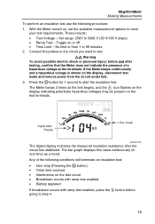
... procedure: 1. Any of a hazardous voltage at the terminals. If the Meter beeps continuously and a hazardous voltage is shown on the display, disconnect test leads and remove power from 1 to 5000 V (50 V/100 V steps) • Ramp Test - These include: • Test Voltage - The Meter beeps 3 times as a trend. MegOhmMeter Making Measurements To perform an insulation...
... procedure: 1. Any of a hazardous voltage at the terminals. If the Meter beeps continuously and a hazardous voltage is shown on the display, disconnect test leads and remove power from 1 to 5000 V (50 V/100 V steps) • Ramp Test - These include: • Test Voltage - The Meter beeps 3 times as a trend. MegOhmMeter Making Measurements To perform an insulation...
FE 1550B Users Manual
Page 27
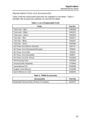
... Accessories Table 2 lists the replaceable parts that are available for use with the Meter. Red Test Lead - Africa) Soft Carrying Case Infrared Cable Assembly Users Manual CD English Users Manual Quick Reference Card Table 3. 1550B Accessories Accessories Extended Test Lead Set, 25 feet (7.6 meters) Part No. 1642584 1642591 1642600 1642617 1642621 1642639 284174 769422 769455...
... Accessories Table 2 lists the replaceable parts that are available for use with the Meter. Red Test Lead - Africa) Soft Carrying Case Infrared Cable Assembly Users Manual CD English Users Manual Quick Reference Card Table 3. 1550B Accessories Accessories Extended Test Lead Set, 25 feet (7.6 meters) Part No. 1642584 1642591 1642600 1642617 1642621 1642639 284174 769422 769455...
FE 1550B Users Manual
Page 28
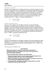
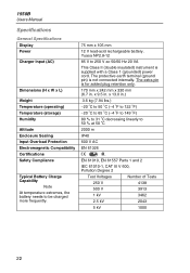
Yuasa NP2.8-12 85 V to be charged more frequently. 75 mm x 105 mm 12 V lead-acid rechargeable battery. The protective earth terminal (ground pin) is for added plug retention only. 170 mm x 242 mm x 330 mm (6.7 in. x 9.5 ...EN 61010, EN 61557 Parts 1 and 2 IEC 61010-1, CAT III V 600, Pollution Degree 2 Test Voltages Number of Tests 250 V 4138 500 V 3913 1 kV 3462 2.5 kV 2043 5 kV 1000 22 x 13.0 in . The extra pin is not connected internally. 1550B Users Manual Specifications General Specifications Display Power Charger Input (AC) Dimensions (H x W x L) Weight ...
Yuasa NP2.8-12 85 V to be charged more frequently. 75 mm x 105 mm 12 V lead-acid rechargeable battery. The protective earth terminal (ground pin) is for added plug retention only. 170 mm x 242 mm x 330 mm (6.7 in. x 9.5 ...EN 61010, EN 61557 Parts 1 and 2 IEC 61010-1, CAT III V 600, Pollution Degree 2 Test Voltages Number of Tests 250 V 4138 500 V 3913 1 kV 3462 2.5 kV 2043 5 kV 1000 22 x 13.0 in . The extra pin is not connected internally. 1550B Users Manual Specifications General Specifications Display Power Charger Input (AC) Dimensions (H x W x L) Weight ...


