
Fluke 1520 MegOhmMeter Datasheet
Page 1
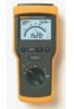
Fluke 1520 MegOhmMeter Technical Data The Fluke 1520 MegOhmMeter is greater than 30V ac or 30V dc. • AC/DC voltage measurement up to 600V • Lo-Ohms function for testing connections • Last reading memory display • 4 C-cell batteries for up to 5,000 tests per EN61557... charges • Heavy duty test leads, alligator clips and test probes • Rugged, splash-proof case with analog bar graph and digital display • Three output voltages for insulation resistance testing: 250V, 500V, 1000V • Insulation resistance testing up to 600V dc switches automatically...
Fluke 1520 MegOhmMeter Technical Data The Fluke 1520 MegOhmMeter is greater than 30V ac or 30V dc. • AC/DC voltage measurement up to 600V • Lo-Ohms function for testing connections • Last reading memory display • 4 C-cell batteries for up to 5,000 tests per EN61557... charges • Heavy duty test leads, alligator clips and test probes • Rugged, splash-proof case with analog bar graph and digital display • Three output voltages for insulation resistance testing: 250V, 500V, 1000V • Insulation resistance testing up to 600V dc switches automatically...
Fluke 1520 MegOhmMeter Datasheet
Page 2
... 241 x 108 x 72mm (9.5 x 4.25 x 2.85 inches) Weight 1.1 kg (2.5 lbs) Batteries 4 C size 1.5V alkaline Warranty 3 years Ordering Information Fluke 1520 MegOhmMeter Included Accessories • Fluke 1520 MegOhmMeter • TL27 Heavy Duty Test Leads (1 Red and 1 Black) • TP74 Lantern Tip Test Probes (1 Red and 1 Black) • AC86 Large Jaw Alligator Clips (1 Red and 1 Black) • Protective holster with...
... 241 x 108 x 72mm (9.5 x 4.25 x 2.85 inches) Weight 1.1 kg (2.5 lbs) Batteries 4 C size 1.5V alkaline Warranty 3 years Ordering Information Fluke 1520 MegOhmMeter Included Accessories • Fluke 1520 MegOhmMeter • TL27 Heavy Duty Test Leads (1 Red and 1 Black) • TP74 Lantern Tip Test Probes (1 Red and 1 Black) • AC86 Large Jaw Alligator Clips (1 Red and 1 Black) • Protective holster with...
FE 1520 Users Manual
Page 6
Fluke 1520 Unpacking the Meter The Fluke Model 1520 MegOhmMeter (hereafter, "the meter") is a handheld instrument designed primarily to make resistance/insulation resistance measurements. The MegOhmMeter includes the following items, see Figure 1: • 2 test leads, red and black, 1.5 m • 2 test probes, red and black • 2 alligator clips, red and black • Hand strap • Carrying case • CD ROM (Not Pictured) 1
Fluke 1520 Unpacking the Meter The Fluke Model 1520 MegOhmMeter (hereafter, "the meter") is a handheld instrument designed primarily to make resistance/insulation resistance measurements. The MegOhmMeter includes the following items, see Figure 1: • 2 test leads, red and black, 1.5 m • 2 test probes, red and black • 2 alligator clips, red and black • Hand strap • Carrying case • CD ROM (Not Pictured) 1
FE 1520 Users Manual
Page 9
Fluke 1520 Users Manual W Safety Information Use of additional operating circuits connected in a manner not specified by the manufacturer may impair safety features/protection provided by transient ... instrument in parallel or by the equipment. Do not use the Meter if it looks damaged. • Be careful when working alone. • Inspect the test leads for damaged insulation or exposed metal. Read the following : • Avoid working above 30 V ac rms, 42 V ac peak and 60 V dc). 4 Such voltages pose...
Fluke 1520 Users Manual W Safety Information Use of additional operating circuits connected in a manner not specified by the manufacturer may impair safety features/protection provided by transient ... instrument in parallel or by the equipment. Do not use the Meter if it looks damaged. • Be careful when working alone. • Inspect the test leads for damaged insulation or exposed metal. Read the following : • Avoid working above 30 V ac rms, 42 V ac peak and 60 V dc). 4 Such voltages pose...

FE 1520 Users Manual
Page 10
... the Meter around explosive gas, vapor or dust. • Disconnect the test leads from power sources and from the Meter before disconnecting the neutral test lead. Do not use the Meter if the battery indicator ( ) shows a battery empty condition. • Use only Fluke recommended batteries and fuse. • Do not use the Meter with any...
... the Meter around explosive gas, vapor or dust. • Disconnect the test leads from power sources and from the Meter before disconnecting the neutral test lead. Do not use the Meter if the battery indicator ( ) shows a battery empty condition. • Use only Fluke recommended batteries and fuse. • Do not use the Meter with any...

FE 1520 Users Manual
Page 12
Backlight button Turns the display backlight ON and OFF. 7 When ON, the R icon appears on the display. Low Resistance function X Turns the test lead resistance compensation ON. The main display indicates 0.00. The icon appears on the display and the Meter beeps at short circuit. To compensate, touch the probe tips together, then press and hold ZERO until the Meter beeps. N Z C MegOhmMeter Key functions Table 1 (continued) Resistance Beeper function Turns the Beeper function ON and OFF.
Backlight button Turns the display backlight ON and OFF. 7 When ON, the R icon appears on the display. Low Resistance function X Turns the test lead resistance compensation ON. The main display indicates 0.00. The icon appears on the display and the Meter beeps at short circuit. To compensate, touch the probe tips together, then press and hold ZERO until the Meter beeps. N Z C MegOhmMeter Key functions Table 1 (continued) Resistance Beeper function Turns the Beeper function ON and OFF.
FE 1520 Users Manual
Page 13
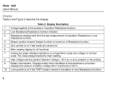
Fluke 1520 Users Manual Display Table 2 and Figure 2 describe the display. Table 2. Displays briefly when the Meter...4 Beeper symbol shows if beeper function is turned on in Resistance function. 5 Zero symbol is on if test leads are zeroed out. 6 Main reading display for all functions. 7 Analog bar graph displays resistance on a logarithmic scale and voltage... on if the TEST mode is locked in increments of 25 %. 10 Lock symbol is present on the probes. 9 Battery life indicator. Display...
Fluke 1520 Users Manual Display Table 2 and Figure 2 describe the display. Table 2. Displays briefly when the Meter...4 Beeper symbol shows if beeper function is turned on in Resistance function. 5 Zero symbol is on if test leads are zeroed out. 6 Main reading display for all functions. 7 Analog bar graph displays resistance on a logarithmic scale and voltage... on if the TEST mode is locked in increments of 25 %. 10 Lock symbol is present on the probes. 9 Battery life indicator. Display...
FE 1520 Users Manual
Page 15
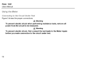
Warning To prevent electric shock when performing resistance tests, remove all W power from the circuit to the circuit under test. 10 Warning To prevent electric shock, first connect the test leads to the Meter inputs before you make connection to be measured. Fluke 1520 Users Manual Using the Meter Connecting to the Circuit Under Test W Figure 3 shows the proper connections.
Warning To prevent electric shock when performing resistance tests, remove all W power from the circuit to the circuit under test. 10 Warning To prevent electric shock, first connect the test leads to the Meter inputs before you make connection to be measured. Fluke 1520 Users Manual Using the Meter Connecting to the Circuit Under Test W Figure 3 shows the proper connections.
FE 1520 Users Manual
Page 21
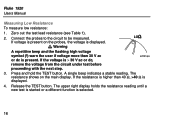
.... 16 Connect the probes to the circuit to be measured. Zero out the test lead resistance (see Table 1). 2. If the resistance is higher than 30 V ac or dc is present on the main display. Fluke 1520 Users Manual Measuring Low Resistance To measure low resistance: 1. W If voltage is... present. The upper right display holds the resistance reading until a new test is started or a different function is > 30 V ac or dc...
.... 16 Connect the probes to the circuit to be measured. Zero out the test lead resistance (see Table 1). 2. If the resistance is higher than 30 V ac or dc is present on the main display. Fluke 1520 Users Manual Measuring Low Resistance To measure low resistance: 1. W If voltage is... present. The upper right display holds the resistance reading until a new test is started or a different function is > 30 V ac or dc...

FE 1520 Users Manual
Page 24
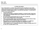
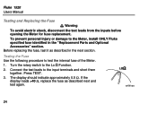
Full 0% - Display Example acf13f.eps 19 Checking the Battery This function tests the battery under simulated load per EN61557. Empty Figure 4. Disconnect all test leads from any circuit. MegOhmMeter Using the Meter Full Empty acf09f.eps 100% -
Full 0% - Display Example acf13f.eps 19 Checking the Battery This function tests the battery under simulated load per EN61557. Empty Figure 4. Disconnect all test leads from any circuit. MegOhmMeter Using the Meter Full Empty acf09f.eps 100% -

FE 1520 Users Manual
Page 26
GTo avoid false readings, which could lead to the OFF position. 2. Disconnect test leads from the inputs before opening the Meter for recycling information. Used batteries should be disposed of these batteries with other solid waste.... Replacing and Disposing of the Batteries Warning To avoid electric shock, disconnect the test leads from any power source. 3. Note This Meter contains alkaline batteries. The Meter uses four alkaline C cell batteries (supplied). Contact your authorized Fluke Service center for battery replacement. Turn the rotary switch to possible electric shock ...
GTo avoid false readings, which could lead to the OFF position. 2. Disconnect test leads from the inputs before opening the Meter for recycling information. Used batteries should be disposed of these batteries with other solid waste.... Replacing and Disposing of the Batteries Warning To avoid electric shock, disconnect the test leads from any power source. 3. Note This Meter contains alkaline batteries. The Meter uses four alkaline C cell batteries (supplied). Contact your authorized Fluke Service center for battery replacement. Turn the rotary switch to possible electric shock ...
FE 1520 Users Manual
Page 29
... the input terminals and short them together. The display should indicate approximately 0.5 Ω. Connect the test leads to the Meter, install ONLY Fluke specified fuse identified in the next section. Fluke 1520 Users Manual W Testing and Replacing the Fuse Warning To avoid electric shock, disconnect the test leads from the inputs before opening the Meter for fuse replacement.
... the input terminals and short them together. The display should indicate approximately 0.5 Ω. Connect the test leads to the Meter, install ONLY Fluke specified fuse identified in the next section. Fluke 1520 Users Manual W Testing and Replacing the Fuse Warning To avoid electric shock, disconnect the test leads from the inputs before opening the Meter for fuse replacement.

FE 1520 Users Manual
Page 30
Disconnect test leads from any power source. 3. Unscrew the bottom cover as follows: 1. If the previous fuse test indicates that the fuse is defective (resistance > 40 Ω), replace the fuse as shown in Figure 6. 6. Place the bottom cover on and secure the...or damage to the Meter, use ONLY the specified fuse, and in the battery compartment. 9. Observe the battery polarity shown in accordance with a new fuse. 7. Test the fuse as described under "Replacing and Disposing of the Batteries". 4. Follow Steps 2 - 5 to the OFF position. 2. Secure the battery access lid. 10...
Disconnect test leads from any power source. 3. Unscrew the bottom cover as follows: 1. If the previous fuse test indicates that the fuse is defective (resistance > 40 Ω), replace the fuse as shown in Figure 6. 6. Place the bottom cover on and secure the...or damage to the Meter, use ONLY the specified fuse, and in the battery compartment. 9. Observe the battery polarity shown in accordance with a new fuse. 7. Test the fuse as described under "Replacing and Disposing of the Batteries". 4. Follow Steps 2 - 5 to the OFF position. 2. Secure the battery access lid. 10...

FE 1520 Users Manual
Page 32
MegOhmMeter Replacement Parts and Optional Accessories Replacement Parts and Optional Accessories Replacement Part Battery 1.5 V Alkaline Size C Test Lead set Test Probe, 1 kV, lantern tip, red Test Probe, 1 kV, lantern tip, black Alligator Clip, red Alligator Clip, black Carrying Case Holster WHand Strap Fuse, 6 mm x 32 mm (0.25 x 1.25 inch), 0.5 A, 660 V, Fast ...
MegOhmMeter Replacement Parts and Optional Accessories Replacement Parts and Optional Accessories Replacement Part Battery 1.5 V Alkaline Size C Test Lead set Test Probe, 1 kV, lantern tip, red Test Probe, 1 kV, lantern tip, black Alligator Clip, red Alligator Clip, black Carrying Case Holster WHand Strap Fuse, 6 mm x 32 mm (0.25 x 1.25 inch), 0.5 A, 660 V, Fast ...
FE 1520 Users Manual
Page 37
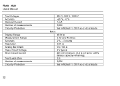
Fluke 1520 Users Manual Test Voltages Accuracy Nominal Current Number of measurements Circuitry Protection Display Range Measurement Range Accuracy Resolution Analog Bar Graph Open Circuit Voltage Short Circuit Current Test Leads Zero Number of measurements Circuitry Protection 32 250 V, 500 V, 1000 V +20 %, -0 % 1 mA 5,000 test inhibited if ≥ 30 V ac or dc at inputs Lo Ω 40...
Fluke 1520 Users Manual Test Voltages Accuracy Nominal Current Number of measurements Circuitry Protection Display Range Measurement Range Accuracy Resolution Analog Bar Graph Open Circuit Voltage Short Circuit Current Test Leads Zero Number of measurements Circuitry Protection 32 250 V, 500 V, 1000 V +20 %, -0 % 1 mA 5,000 test inhibited if ≥ 30 V ac or dc at inputs Lo Ω 40...


