Fluke 1520 MegOhmMeter Datasheet
Page 2
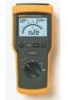
... x 72mm (9.5 x 4.25 x 2.85 inches) Weight 1.1 kg (2.5 lbs) Batteries 4 C size 1.5V alkaline Warranty 3 years Ordering Information Fluke 1520 MegOhmMeter Included Accessories • Fluke 1520 MegOhmMeter • TL27 Heavy Duty Test Leads (1 Red and 1 Black) • TP74 Lantern Tip Test Probes (1 Red and 1 Black) &#...• SH 100 Shoulder Strap • TPAK Strap and Magnet for hanging the Fluke 1520 Optional TPAK Meter Strap and Magnet Hanging Kit Optional SH 100 Shoulder Strap Fluke. Safety Specifications Electrical safety Meets IEC 1010-1 and EN 61557 Protection class Pollution degree...
... x 72mm (9.5 x 4.25 x 2.85 inches) Weight 1.1 kg (2.5 lbs) Batteries 4 C size 1.5V alkaline Warranty 3 years Ordering Information Fluke 1520 MegOhmMeter Included Accessories • Fluke 1520 MegOhmMeter • TL27 Heavy Duty Test Leads (1 Red and 1 Black) • TP74 Lantern Tip Test Probes (1 Red and 1 Black) &#...• SH 100 Shoulder Strap • TPAK Strap and Magnet for hanging the Fluke 1520 Optional TPAK Meter Strap and Magnet Hanging Kit Optional SH 100 Shoulder Strap Fluke. Safety Specifications Electrical safety Meets IEC 1010-1 and EN 61557 Protection class Pollution degree...

FE 1520 Users Manual
Page 3
Table of Contents Title Page Unpacking the Meter 1 Safety Information and Symbols 3 Key functions ...6 Display ...8 Using the Meter 10 Connecting to the Circuit Under Test 10 Auto-Shut-Off 12 Measuring Insulation Resistance 12 Measuring Low Resistance 16 Measuring Resistance 18 Measuring Voltage 18 Checking the Battery 19 Maintaining the Meter 20 Cleaning...20 Replacing and Disposing of the Batteries 21 Testing and Replacing the Fuse 24 Replacement Parts and Optional Accessories 27 Principle of Measurement for Resistance 28 Service Centers 28 Specifications...29 i
Table of Contents Title Page Unpacking the Meter 1 Safety Information and Symbols 3 Key functions ...6 Display ...8 Using the Meter 10 Connecting to the Circuit Under Test 10 Auto-Shut-Off 12 Measuring Insulation Resistance 12 Measuring Low Resistance 16 Measuring Resistance 18 Measuring Voltage 18 Checking the Battery 19 Maintaining the Meter 20 Cleaning...20 Replacing and Disposing of the Batteries 21 Testing and Replacing the Fuse 24 Replacement Parts and Optional Accessories 27 Principle of Measurement for Resistance 28 Service Centers 28 Specifications...29 i
FE 1520 Users Manual
Page 6
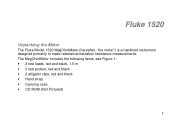
The MegOhmMeter includes the following items, see Figure 1: • 2 test leads, red and black, 1.5 m • 2 test probes, red and black • 2 alligator clips, red and black • Hand strap • Carrying case • CD ROM (Not Pictured) 1 Fluke 1520 Unpacking the Meter The Fluke Model 1520 MegOhmMeter (hereafter, "the meter") is a handheld instrument designed primarily to make resistance/insulation resistance measurements.
The MegOhmMeter includes the following items, see Figure 1: • 2 test leads, red and black, 1.5 m • 2 test probes, red and black • 2 alligator clips, red and black • Hand strap • Carrying case • CD ROM (Not Pictured) 1 Fluke 1520 Unpacking the Meter The Fluke Model 1520 MegOhmMeter (hereafter, "the meter") is a handheld instrument designed primarily to make resistance/insulation resistance measurements.

FE 1520 Users Manual
Page 8
International symbols on the Meter and in fixed installations (e.g., electricity meter and primary over-current protection equipment. 3 Equipment of Impulse Withstand Voltage protection provided. MegOhmMeter Safety Information and Symbols W Safety Information ...pose hazard(s) to the level of OVERVOLTAGE CATEGORY ,,, is equipment in the manual are explained below. A Warning identifies conditions and actions that may damage the Meter. Y Risk of electric shock J Earth W See manual I Fuse T Equipment protected by double or reinforced Insulation D AC or DC M Battery Recycling ...
International symbols on the Meter and in fixed installations (e.g., electricity meter and primary over-current protection equipment. 3 Equipment of Impulse Withstand Voltage protection provided. MegOhmMeter Safety Information and Symbols W Safety Information ...pose hazard(s) to the level of OVERVOLTAGE CATEGORY ,,, is equipment in the manual are explained below. A Warning identifies conditions and actions that may damage the Meter. Y Risk of electric shock J Earth W See manual I Fuse T Equipment protected by double or reinforced Insulation D AC or DC M Battery Recycling ...
FE 1520 Users Manual
Page 9
... affected by impedances of instrument in parallel or by the equipment. Do not use the Meter if it looks damaged. • Be careful when working alone. • Inspect the test leads for damaged insulation or exposed metal. Fluke 1520 Users Manual W Safety Information Use of additional operating circuits connected in a manner not specified...
... affected by impedances of instrument in parallel or by the equipment. Do not use the Meter if it looks damaged. • Be careful when working alone. • Inspect the test leads for damaged insulation or exposed metal. Fluke 1520 Users Manual W Safety Information Use of additional operating circuits connected in a manner not specified...

FE 1520 Users Manual
Page 10
... test leads in a wet environment. • Use only Fluke specified test leads. 5 Do not use the Meter if the battery indicator ( ) shows a battery empty condition. • Use only Fluke recommended batteries and fuse. • Do not use the Meter with any parts or cover removed. • Do not ...use the Meter in proper input terminals. Disconnect the live test lead before changing the batteries...
... test leads in a wet environment. • Use only Fluke specified test leads. 5 Do not use the Meter if the battery indicator ( ) shows a battery empty condition. • Use only Fluke recommended batteries and fuse. • Do not use the Meter with any parts or cover removed. • Do not ...use the Meter in proper input terminals. Disconnect the live test lead before changing the batteries...

FE 1520 Users Manual
Page 12
When ON, the R icon appears on the display. The main display indicates 0.00. To compensate, touch the probe tips together, then press and hold ZERO until the Meter beeps. Backlight button Turns the display backlight ON and OFF. 7 Low Resistance function X Turns the test lead resistance compensation ON. N Z C MegOhmMeter Key functions Table 1 (continued) Resistance Beeper function Turns the Beeper function ON and OFF. The icon appears on the display and the Meter beeps at short circuit.
When ON, the R icon appears on the display. The main display indicates 0.00. To compensate, touch the probe tips together, then press and hold ZERO until the Meter beeps. Backlight button Turns the display backlight ON and OFF. 7 Low Resistance function X Turns the test lead resistance compensation ON. N Z C MegOhmMeter Key functions Table 1 (continued) Resistance Beeper function Turns the Beeper function ON and OFF. The icon appears on the display and the Meter beeps at short circuit.
FE 1520 Users Manual
Page 13
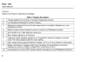
... all functions. 7 Analog bar graph displays resistance on a logarithmic scale and voltage on if the TEST mode is on a linear scale. Displays briefly when the Meter is present on the probes. 9 Battery life indicator. Table 2. Fluke 1520 Users Manual Display Table 2 and Figure 2 describe the display.
... all functions. 7 Analog bar graph displays resistance on a logarithmic scale and voltage on if the TEST mode is on a linear scale. Displays briefly when the Meter is present on the probes. 9 Battery life indicator. Table 2. Fluke 1520 Users Manual Display Table 2 and Figure 2 describe the display.
FE 1520 Users Manual
Page 15
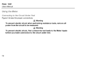
Warning To prevent electric shock, first connect the test leads to the Meter inputs before you make connection to the Circuit Under Test W Figure 3 shows the proper connections. Fluke 1520 Users Manual Using the Meter Connecting to the circuit under test. 10 Warning To prevent electric shock when performing resistance tests, remove all W power from the circuit to be measured.
Warning To prevent electric shock, first connect the test leads to the Meter inputs before you make connection to the Circuit Under Test W Figure 3 shows the proper connections. Fluke 1520 Users Manual Using the Meter Connecting to the circuit under test. 10 Warning To prevent electric shock when performing resistance tests, remove all W power from the circuit to be measured.

FE 1520 Users Manual
Page 16
MegOhmMeter Using the Meter Figure 3. Connecting to the Circuit Under Test acf04f.eps 11
MegOhmMeter Using the Meter Figure 3. Connecting to the Circuit Under Test acf04f.eps 11
FE 1520 Users Manual
Page 17
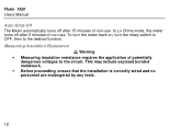
To turn the meter back on, turn the rotary switch to OFF, then to the circuit. This may include exposed bonded metalwork. • Before proceeding, ensure that the installation is correctly wired and no personnel are endangered by any tests. 12 In Lo Ohms mode, the meter turns off after 5 minutes of non-use . Fluke 1520 Users Manual Auto-Shut-Off The Meter automatically turns off after 15 minutes of non-use . W Measuring Insulation Resistance Warning • Measuring insulation resistance requires the application of potentially dangerous voltages to the desired function.
To turn the meter back on, turn the rotary switch to OFF, then to the circuit. This may include exposed bonded metalwork. • Before proceeding, ensure that the installation is correctly wired and no personnel are endangered by any tests. 12 In Lo Ohms mode, the meter turns off after 5 minutes of non-use . Fluke 1520 Users Manual Auto-Shut-Off The Meter automatically turns off after 15 minutes of non-use . W Measuring Insulation Resistance Warning • Measuring insulation resistance requires the application of potentially dangerous voltages to the desired function.

FE 1520 Users Manual
Page 18
... dc is > 30 V ac or dc, remove the voltage from the circuit under test. Push and hold the TEST button. Select the test voltage. 2. The meter automatically detects if the circuit is pushed. 13 until the TEST button is energized, W and displays the detected voltage. The upper left display shows the... test voltage applied to be measured. Note The display shows - - - - MegOhmMeter Using the Meter To measure insulation resistance, do the following: 1. The main display shows the resistance.
... dc is > 30 V ac or dc, remove the voltage from the circuit under test. Push and hold the TEST button. Select the test voltage. 2. The meter automatically detects if the circuit is pushed. 13 until the TEST button is energized, W and displays the detected voltage. The upper left display shows the... test voltage applied to be measured. Note The display shows - - - - MegOhmMeter Using the Meter To measure insulation resistance, do the following: 1. The main display shows the resistance.
FE 1520 Users Manual
Page 19
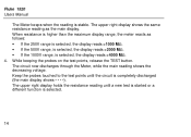
... now discharges through the Meter, while the main reading shows the decreasing voltage. Keep the probes touched to the test points until a new test is started or a different function is selected, the display reads >4000 MΩ. 4. Fluke 1520 Users Manual The Meter beeps when the reading is... higher than the maximum display range, the meter reacts as the main display. When resistance is stable. While keeping the probes on the test ...
... now discharges through the Meter, while the main reading shows the decreasing voltage. Keep the probes touched to the test points until a new test is started or a different function is selected, the display reads >4000 MΩ. 4. Fluke 1520 Users Manual The Meter beeps when the reading is... higher than the maximum display range, the meter reacts as the main display. When resistance is stable. While keeping the probes on the test ...

FE 1520 Users Manual
Page 20
... to the probes. To use the LOCK function: 1. W Warning In this mode, if the probes are disconnected from the circuit, the Meter cannot discharge any potentially dangerous capacitive voltages left on the probes. Caution In this mode. 2. Ensure that the circuit is de-energized before connecting... Resistance The LOCK function holds the test voltage on the circuit. In this mode a potentially dangerous voltage is live. MegOhmMeter Using the Meter Using the LOCK Function to push and hold the TEST button. Press the TEST button, then press the LOCK button, and then release...
... to the probes. To use the LOCK function: 1. W Warning In this mode, if the probes are disconnected from the circuit, the Meter cannot discharge any potentially dangerous capacitive voltages left on the probes. Caution In this mode. 2. Ensure that the circuit is de-energized before connecting... Resistance The LOCK function holds the test voltage on the circuit. In this mode a potentially dangerous voltage is live. MegOhmMeter Using the Meter Using the LOCK Function to push and hold the TEST button. Press the TEST button, then press the LOCK button, and then release...

FE 1520 Users Manual
Page 22
... indicate if the circuit is useful to push and hold the TEST button for both simultaneously. 2. The reading should be tested. MegOhmMeter Using the Meter 5. This test is live in this mode. Ensure that the circuit is used to continuously supply the test current to the circuit to disengage the ...
... indicate if the circuit is useful to push and hold the TEST button for both simultaneously. 2. The reading should be tested. MegOhmMeter Using the Meter 5. This test is live in this mode. Ensure that the circuit is used to continuously supply the test current to the circuit to disengage the ...
FE 1520 Users Manual
Page 23
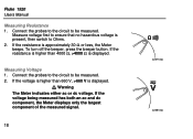
If the resistance is displayed. Measuring Voltage 1. Warning The Meter indicates either ac or dc voltage. If the voltage is higher than 4000 Ω, >4000 Ω is present, then switch to be measured. Fluke 1520 Users Manual Measuring Resistance 1. To turn off the beeper, press the beeper button. ... circuit to ensure that no hazardous voltage is displayed. W 2. If the voltage being measured has both an ac and dc component, the Meter displays only the largest component of the measured signal. 18 acf07f.eps acf08f.eps If the resistance is higher than 660 V, >660 V ...
If the resistance is displayed. Measuring Voltage 1. Warning The Meter indicates either ac or dc voltage. If the voltage is higher than 4000 Ω, >4000 Ω is present, then switch to be measured. Fluke 1520 Users Manual Measuring Resistance 1. To turn off the beeper, press the beeper button. ... circuit to ensure that no hazardous voltage is displayed. W 2. If the voltage being measured has both an ac and dc component, the Meter displays only the largest component of the measured signal. 18 acf07f.eps acf08f.eps If the resistance is higher than 660 V, >660 V ...

FE 1520 Users Manual
Page 24
Checking the Battery This function tests the battery under simulated load per EN61557. Disconnect all test leads from any circuit. Full 0% - MegOhmMeter Using the Meter Full Empty acf09f.eps 100% - Display Example acf13f.eps 19 Empty Figure 4.
Checking the Battery This function tests the battery under simulated load per EN61557. Disconnect all test leads from any circuit. Full 0% - MegOhmMeter Using the Meter Full Empty acf09f.eps 100% - Display Example acf13f.eps 19 Empty Figure 4.

FE 1520 Users Manual
Page 25
Periodically wipe the case with soap and water. Fluke 1520 Users Manual Maintaining the Meter This section provides basic maintenance information, including fuse and battery replacement instructions. Caution Do not attempt to repair or service your Meter unless you are qualified to do so and have the relevant calibration, performance test, and service information. Do not use abrasives or solvents. 20 Remove any residue afterwards. Cleaning Clean only with a damp cloth and mild detergent.
Periodically wipe the case with soap and water. Fluke 1520 Users Manual Maintaining the Meter This section provides basic maintenance information, including fuse and battery replacement instructions. Caution Do not attempt to repair or service your Meter unless you are qualified to do so and have the relevant calibration, performance test, and service information. Do not use abrasives or solvents. 20 Remove any residue afterwards. Cleaning Clean only with a damp cloth and mild detergent.

FE 1520 Users Manual
Page 26
...batteries, do the following (see Figure 5): 1. Disconnect test leads from the inputs before opening the Meter for recycling information. Contact your authorized Fluke Service center for battery replacement. Do not dispose of by a qualified recycler or hazardous materials handler. ...MegOhmMeter Maintaining the Meter W Replacing and Disposing of the Batteries Warning To avoid electric shock, disconnect the ...
...batteries, do the following (see Figure 5): 1. Disconnect test leads from the inputs before opening the Meter for recycling information. Contact your authorized Fluke Service center for battery replacement. Do not dispose of by a qualified recycler or hazardous materials handler. ...MegOhmMeter Maintaining the Meter W Replacing and Disposing of the Batteries Warning To avoid electric shock, disconnect the ...
FE 1520 Users Manual
Page 27
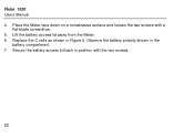
Lift the battery access lid away from the Meter. 6. Observe the battery polarity shown in Figure 5. Secure the battery access lid back in position with a flat-blade screwdriver. 5. Replace the C cells as shown in the battery compartment. 7. Place the Meter face down on a nonabrasive surface and loosen the two screws with the two screws. 22 Fluke 1520 Users Manual 4.
Lift the battery access lid away from the Meter. 6. Observe the battery polarity shown in Figure 5. Secure the battery access lid back in position with a flat-blade screwdriver. 5. Replace the C cells as shown in the battery compartment. 7. Place the Meter face down on a nonabrasive surface and loosen the two screws with the two screws. 22 Fluke 1520 Users Manual 4.


