

Fluke 114,115,117 Manual
Page 1
Printed in China All product names are trademarks of their respective companies. ® 114, 115, and 117 True-rms Multimeters Users Manual PN 2572573 July 2006, Rev. 1, 2/07 © 2006, 2007 Fluke Corporation, All rights reserved.
Printed in China All product names are trademarks of their respective companies. ® 114, 115, and 117 True-rms Multimeters Users Manual PN 2572573 July 2006, Rev. 1, 2/07 © 2006, 2007 Fluke Corporation, All rights reserved.
Fluke 114,115,117 Manual
Page 3
...31 402-675-200 Japan: +81-3-3434-0181 Singapore +65-738-5655 Anywhere in an incorrect terminal. Register your Meter at www.fluke.com. These meters meet CAT III IEC 61010-1 2nd Edition standards. Test Lead Alert XWWarning Personal injury or damage to the Meter can...rms multimeters (hereafter "the Meter") with a lead in the world: +1-425-446-5500 Visit Fluke's web site at register.fluke.com. True-rms Multimeters Introduction The Fluke Model 114, Model 115, and Model 117 are designed to protect against transients in the correct terminals, LEAd is displayed when the Meter measures...
...31 402-675-200 Japan: +81-3-3434-0181 Singapore +65-738-5655 Anywhere in an incorrect terminal. Register your Meter at www.fluke.com. These meters meet CAT III IEC 61010-1 2nd Edition standards. Test Lead Alert XWWarning Personal injury or damage to the Meter can...rms multimeters (hereafter "the Meter") with a lead in the world: +1-425-446-5500 Visit Fluke's web site at register.fluke.com. True-rms Multimeters Introduction The Fluke Model 114, Model 115, and Model 117 are designed to protect against transients in the correct terminals, LEAd is displayed when the Meter measures...
Fluke 114,115,117 Manual
Page 4
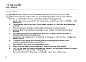
... 60 V dc. These voltages pose a shock hazard. • Disconnect circuit power and discharge all high-voltage capacitors before opening the battery door or Meter case. 2 114, 115, and 117 Users Manual Safety Information A "XWWarning" statement identifies hazardous conditions and actions that could cause bodily harm or death.
... 60 V dc. These voltages pose a shock hazard. • Disconnect circuit power and discharge all high-voltage capacitors before opening the battery door or Meter case. 2 114, 115, and 117 Users Manual Safety Information A "XWWarning" statement identifies hazardous conditions and actions that could cause bodily harm or death.
Fluke 114,115,117 Manual
Page 6
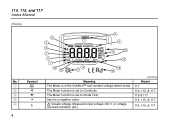
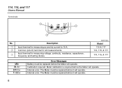
edy02f.eps Model 117 114, 115, & 117 115 & 117 114, 115, & 117 114, 115, & 117 A B C D E 4 Symbol w s R O Y 6 5 4 3 2 1 16 15 VoltAlert 7 14 17 8 9 10 11 12 13 18 Meaning The Meter is a negative value. Measured input voltage ≥30 V, or voltage overload condition (OL). X Unsafe voltage. The Meter function is set to Continuity. 114, 115, and 117 Users Manual Display No. The Meter function is set to Diode Test Input is in the VoltAlert™ non-contact voltage detect mode.
edy02f.eps Model 117 114, 115, & 117 115 & 117 114, 115, & 117 114, 115, & 117 A B C D E 4 Symbol w s R O Y 6 5 4 3 2 1 16 15 VoltAlert 7 14 17 8 9 10 11 12 13 18 Meaning The Meter is a negative value. Measured input voltage ≥30 V, or voltage overload condition (OL). X Unsafe voltage. The Meter function is set to Continuity. 114, 115, and 117 Users Manual Display No. The Meter function is set to Diode Test Input is in the VoltAlert™ non-contact voltage detect mode.
Fluke 114,115,117 Manual
Page 7
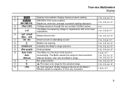
... capacitance with a low input impedance. 114, 115 & 117 J nµF mVµA MkΩ kHz Measurement units. 114, 115, & 117 K DC AC Direct current or alternating current 114, 115 & 117 L N Battery low warning. 114, 115, & 117 M 610000 mV Indicates the Meter's range selection. 114, 115, & 117 N (Bar graph) Analog display. 114, 115, & 117 O Auto Volts The Meter is too large for best resolution. 114, 115, & 117 Manual Manual ranging. The Meter selects...
... capacitance with a low input impedance. 114, 115 & 117 J nµF mVµA MkΩ kHz Measurement units. 114, 115, & 117 K DC AC Direct current or alternating current 114, 115 & 117 L N Battery low warning. 114, 115, & 117 M 610000 mV Indicates the Meter's range selection. 114, 115, & 117 N (Bar graph) Analog display. 114, 115, & 117 O Auto Volts The Meter is too large for best resolution. 114, 115, & 117 Manual Manual ranging. The Meter selects...
Fluke 114,115,117 Manual
Page 8
... Manual Terminals 1 V A COM 3 10 A FUSED 2 No. edy01f.eps Model 115 & 117 114, 115, & 117 114, 115, & 117 bAtt CAL Err EEPr Err F11 Err Error Messages Battery must be replaced before it will operate. C Input terminal for all measurements. The Meter ...
... Manual Terminals 1 V A COM 3 10 A FUSED 2 No. edy01f.eps Model 115 & 117 114, 115, & 117 114, 115, & 117 bAtt CAL Err EEPr Err F11 Err Error Messages Battery must be replaced before it will operate. C Input terminal for all measurements. The Meter ...

Fluke 114,115,117 Manual
Page 9
...ac-coupled. AC current from 0.1 A to 10 A (>10 to 600 V. Non-contact sensing of ac voltage. 115 & 117 115 & 117 115 & 117 115 & 117 117 Note: All ac functions and Auto-V LoZ are dc-coupled. 7 DC voltage from 0.1 to 600 mV. 114 & 117 114, 115 & 117 115 & 117 114, 115 & 117 114, 115 & 117 Ω Ohms from .001 V to 20 A, 30 seconds on at < 20 Ω and turns off ). ... Switch Position Measurement Function Model x e Hz (button) D l Automatically selects ac or dc volts based on , 10 minutes off at >250 Ω. 114, 115 & 117 114, 115 & 117 R S j Hz (button) I w Diode Test.
...ac-coupled. AC current from 0.1 A to 10 A (>10 to 600 V. Non-contact sensing of ac voltage. 115 & 117 115 & 117 115 & 117 115 & 117 117 Note: All ac functions and Auto-V LoZ are dc-coupled. 7 DC voltage from 0.1 to 600 mV. 114 & 117 114, 115 & 117 115 & 117 114, 115 & 117 114, 115 & 117 Ω Ohms from .001 V to 20 A, 30 seconds on at < 20 Ω and turns off ). ... Switch Position Measurement Function Model x e Hz (button) D l Automatically selects ac or dc volts based on , 10 minutes off at >250 Ω. 114, 115 & 117 114, 115 & 117 R S j Hz (button) I w Diode Test.
Fluke 114,115,117 Manual
Page 10
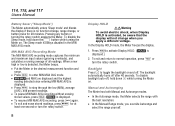
..., hold down the g button while turning the Meter on and off after 40 seconds. The Sleep mode is displayed.) 2. The backlight automatically turns off . 114, 115, and 117 Users Manual Battery Saver ("Sleep Mode") The Meter automatically enters "Sleep mode" and blanks the display if there is no function change, range change when...
..., hold down the g button while turning the Meter on and off after 40 seconds. The Sleep mode is displayed.) 2. The backlight automatically turns off . 114, 115, and 117 Users Manual Battery Saver ("Sleep Mode") The Meter automatically enters "Sleep mode" and blanks the display if there is no function change, range change when...
Fluke 114,115,117 Manual
Page 12
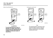
For maximum accuracy in making resistance measurements, use the Meter's resistance (e) function. 114, 115, and 117 Users Manual Measuring Resistance Testing for Continuity XWWarning edy04f.eps To avoid electric shock, injury, or damage to the Meter, disconnect circuit power and discharge all highvoltage capacitors before testing resistance, continuity, diodes, or capacitance. 10 edy06f.eps Note The continuity function works best as a fast, convenient method to check for opens and shorts.
For maximum accuracy in making resistance measurements, use the Meter's resistance (e) function. 114, 115, and 117 Users Manual Measuring Resistance Testing for Continuity XWWarning edy04f.eps To avoid electric shock, injury, or damage to the Meter, disconnect circuit power and discharge all highvoltage capacitors before testing resistance, continuity, diodes, or capacitance. 10 edy06f.eps Note The continuity function works best as a fast, convenient method to check for opens and shorts.

Fluke 114,115,117 Manual
Page 14
114, 115, and 117 Users Manual Measuring AC or DC Current (115 & 117) XWWarning To avoid personal injury or damage to the Meter: • Never attempt to make an in-circuit current measurement when the opencircuit potential to ...
114, 115, and 117 Users Manual Measuring AC or DC Current (115 & 117) XWWarning To avoid personal injury or damage to the Meter: • Never attempt to make an in-circuit current measurement when the opencircuit potential to ...

Fluke 114,115,117 Manual
Page 15
True-rms Multimeters Making Basic Measurements Measuring Capacitance (115 & 117 only) edy14f.eps edy05f.eps 13 Measuring Current above 10 Amps The millivolt and voltage function of the Meter. Refer to measure currents that exceed the rating of the Meter can be used with an optional mV/A output Current Probe to a Fluke catalog or contact your local Fluke representative for your current probe. Make sure the Meter has the correct function selected, AC or DC, for compatible current clamps.
True-rms Multimeters Making Basic Measurements Measuring Capacitance (115 & 117 only) edy14f.eps edy05f.eps 13 Measuring Current above 10 Amps The millivolt and voltage function of the Meter. Refer to measure currents that exceed the rating of the Meter can be used with an optional mV/A output Current Probe to a Fluke catalog or contact your local Fluke representative for your current probe. Make sure the Meter has the correct function selected, AC or DC, for compatible current clamps.
Fluke 114,115,117 Manual
Page 16
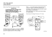
... measurement function on and off. Detecting AC Voltage Presence (117 only) VoltAlert Hot Neutral VoltAlert RANGE Lo edy09f.eps The Meter measures the frequency of a signal by counting the number of the measured signal is 0 V, 0 A for a stable reading. 114, 115, and 117 Users Manual Measuring Frequency (115 & 117 only) XWWarning To avoid electrical shock, disregard the...
... measurement function on and off. Detecting AC Voltage Presence (117 only) VoltAlert Hot Neutral VoltAlert RANGE Lo edy09f.eps The Meter measures the frequency of a signal by counting the number of the measured signal is 0 V, 0 A for a stable reading. 114, 115, and 117 Users Manual Measuring Frequency (115 & 117 only) XWWarning To avoid electrical shock, disregard the...

Fluke 114,115,117 Manual
Page 17
... indication when voltage is turned off or goes into LoZ, (low input impedance) Capacitance mode. Making Low Impedance Capacitance Measurements (115 & 117 only) For making capacitance measurements on flush mounted wall sockets, power strips, flush mounted industrial outlets and various power cords. This... sockets where the actual ac voltage is recessed within the connector itself. True-rms Multimeters Making Basic Measurements Testing Diodes (115 & 117) Good Diode Good Diode Forward Bias Single Beep Bad Diode Reverse Bias Bad Diode Open and Shorted edy07f.eps 15 There...
... indication when voltage is turned off or goes into LoZ, (low input impedance) Capacitance mode. Making Low Impedance Capacitance Measurements (115 & 117 only) For making capacitance measurements on flush mounted wall sockets, power strips, flush mounted industrial outlets and various power cords. This... sockets where the actual ac voltage is recessed within the connector itself. True-rms Multimeters Making Basic Measurements Testing Diodes (115 & 117) Good Diode Good Diode Forward Bias Single Beep Bad Diode Reverse Bias Bad Diode Open and Shorted edy07f.eps 15 There...

Fluke 114,115,117 Manual
Page 18
114, 115, and 117 Users Manual Using the Bargraph The bar graph is disabled when measuring capacitance. It has an overload indicator (>) to the right and a polarity indicator (+)to the full-scale value of the scale. In the 60 V range, for making peak and null adjustments. Testing the Fuse (115 & 117 only) Test fuse as shown...
114, 115, and 117 Users Manual Using the Bargraph The bar graph is disabled when measuring capacitance. It has an overload indicator (>) to the right and a polarity indicator (+)to the full-scale value of the scale. In the 60 V range, for making peak and null adjustments. Testing the Fuse (115 & 117 only) Test fuse as shown...
Fluke 114,115,117 Manual
Page 20
... Wipe the case with an 11 A, 1000 V, FAST fuse having a minimum interrupt rating of 17,000 A. Remove two screws from the case top. 5. Use only Fluke PN 803293. 6. Dirt or moisture in the terminals can affect readings. 18 To re-assemble the Meter, first attach the case bottom to clean the... to the case top, then install the two screws. Finally, insert the Meter into its holder and replace it with a damp cloth and mild detergent. 114, 115, and 117 Users Manual To open the case for fuse replacement: 1. Remove the fuse from its holster.
... Wipe the case with an 11 A, 1000 V, FAST fuse having a minimum interrupt rating of 17,000 A. Remove two screws from the case top. 5. Use only Fluke PN 803293. 6. Dirt or moisture in the terminals can affect readings. 18 To re-assemble the Meter, first attach the case bottom to clean the... to the case top, then install the two screws. Finally, insert the Meter into its holder and replace it with a damp cloth and mild detergent. 114, 115, and 117 Users Manual To open the case for fuse replacement: 1. Remove the fuse from its holster.
Fluke 114,115,117 Manual
Page 21
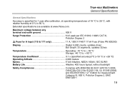
... between any terminal and earth ground 600 V Surge Protection 6 kV peak per IEC 61010-1 600V CAT III, Pollution Degree 2 W Fuse for A input (115 & 117 only 11 A, 1000 V FAST 17 kA Fuse (Fluke PN 803293) Display Digital: 6,000 counts, updates 4/sec Bar Graph: 33 segments, updates 32/sec Temperature Operating: -10 °C to + 50...-rms Multimeters General Specifications General Specifications Accuracy is specified for measurement Category III, 600 V, Pollution Degree 2, EMC EN61326-1 19 Extended specifications are available at www.Fluke.com.
... between any terminal and earth ground 600 V Surge Protection 6 kV peak per IEC 61010-1 600V CAT III, Pollution Degree 2 W Fuse for A input (115 & 117 only 11 A, 1000 V FAST 17 kA Fuse (Fluke PN 803293) Display Digital: 6,000 counts, updates 4/sec Bar Graph: 33 segments, updates 32/sec Temperature Operating: -10 °C to + 50...-rms Multimeters General Specifications General Specifications Accuracy is specified for measurement Category III, 600 V, Pollution Degree 2, EMC EN61326-1 19 Extended specifications are available at www.Fluke.com.

Fluke 114,115,117 Manual
Page 22
114, 115, and 117 Users Manual Certifications UL, P, CSA, TÜV, ; (N10140), VDE IP Rating (dust and water protection IP42 Table 1. Accuracy Specifications Function DC millivolts DC Volts Range 600.0 ...] + [Counts]) 0.1 mV 0.001 V 0.01 V 0.1 V 0.1 V 0.1 mV 0.5 % + 2 0.5 % + 2 DC, 45 to 500 Hz 2.0 % + 3 45 to 500 Hz 1.0 % + 3 500 Hz to 1 kHz 4.0 % + 3 500 Hz to 1 kHz 2.0 % + 3 0.001 V 0.01 V 0.1 V 1.0 % + 3 2.0 % + 3 Model 114, 115, 117 114, 115, 117 114, 117 114, 115, 117 114, 115, 117 20
114, 115, and 117 Users Manual Certifications UL, P, CSA, TÜV, ; (N10140), VDE IP Rating (dust and water protection IP42 Table 1. Accuracy Specifications Function DC millivolts DC Volts Range 600.0 ...] + [Counts]) 0.1 mV 0.001 V 0.01 V 0.1 V 0.1 V 0.1 mV 0.5 % + 2 0.5 % + 2 DC, 45 to 500 Hz 2.0 % + 3 45 to 500 Hz 1.0 % + 3 500 Hz to 1 kHz 4.0 % + 3 500 Hz to 1 kHz 2.0 % + 3 0.001 V 0.01 V 0.1 V 1.0 % + 3 2.0 % + 3 Model 114, 115, 117 114, 115, 117 114, 117 114, 115, 117 114, 115, 117 20

Fluke 114,115,117 Manual
Page 23
....00 μF 100.0 μF 9999 μF 1 nF 0.01 μF 0.1 μF 1 μF 1.9 % + 2 1.9 % + 2 1.9 % + 2 100 μF - 1000 μF: 1.9 % + 2 > 1000 μF: 5 % + 20 1 nF to 500 μF 10% + 2 typical Model 114, 115, 117 114, 115, 117 115, 117 115, 117 115, 117 21
....00 μF 100.0 μF 9999 μF 1 nF 0.01 μF 0.1 μF 1 μF 1.9 % + 2 1.9 % + 2 1.9 % + 2 100 μF - 1000 μF: 1.9 % + 2 > 1000 μF: 5 % + 20 1 nF to 500 μF 10% + 2 typical Model 114, 115, 117 114, 115, 117 115, 117 115, 117 115, 117 21

Fluke 114,115,117 Manual
Page 24
... A input)[2] 999.9 Hz 9.999 kHz 50.00 kHz 0.01 Hz 0.1 Hz 0.001 kHz 0.01 kHz 0.1 % + 2 115, 117 Notes: [1] All ac ranges except Auto-V LoZ are specified from 1 % to 50 kHz. Auto-V LoZ is ac-coupled. 114, 115, and 117 Users Manual Table 1 Accuracy Specifications (cont.) Function Range Resolution Accuracy ± ([% of Reading] + [Counts]) Model AC...
... A input)[2] 999.9 Hz 9.999 kHz 50.00 kHz 0.01 Hz 0.1 Hz 0.001 kHz 0.01 kHz 0.1 % + 2 115, 117 Notes: [1] All ac ranges except Auto-V LoZ are specified from 1 % to 50 kHz. Auto-V LoZ is ac-coupled. 114, 115, and 117 Users Manual Table 1 Accuracy Specifications (cont.) Function Range Resolution Accuracy ± ([% of Reading] + [Counts]) Model AC...

Fluke 114,115,117 Manual
Page 26
114, 115, and 117 Users Manual 24
114, 115, and 117 Users Manual 24
