
Owner Manual
Page 1
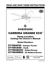
Chalk CF788GBZ00 - BP7427-2 ETL Model No.: CF788 Oil Rubbed Bronze Net Weight: 17.2 Lbs. F40BP74270002 54", 60" or 72" Fan Blades Not Included Form No. Gilded Bronze CF788ORB00 - READ AND SAVE THESE INSTRUCTIONS CARRERA GRANDE ECO™ Damp Location Ceiling Fan Owner's Manual Model Numbers CF788AP00 - Antique Pewter CF788CK00 - Part No.
Chalk CF788GBZ00 - BP7427-2 ETL Model No.: CF788 Oil Rubbed Bronze Net Weight: 17.2 Lbs. F40BP74270002 54", 60" or 72" Fan Blades Not Included Form No. Gilded Bronze CF788ORB00 - READ AND SAVE THESE INSTRUCTIONS CARRERA GRANDE ECO™ Damp Location Ceiling Fan Owner's Manual Model Numbers CF788AP00 - Antique Pewter CF788CK00 - Part No.
Owner Manual
Page 2
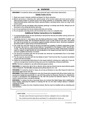
... wiring your owner's manual carefully and keep it for future use only those parts supplied with this product by Emerson Electric Co. Do not operate reversing switch until fan blades have your fan installed by Rhine Electric Co., Ltd. The ceiling fan must be locked, securely fasten a warning device, such as a tag, to be grounded as "Acceptable for use the mounting screws provided with fan speed control, Model No. Most outlet boxes commonly used for support of control...
... wiring your owner's manual carefully and keep it for future use only those parts supplied with this product by Emerson Electric Co. Do not operate reversing switch until fan blades have your fan installed by Rhine Electric Co., Ltd. The ceiling fan must be locked, securely fasten a warning device, such as a tag, to be grounded as "Acceptable for use the mounting screws provided with fan speed control, Model No. Most outlet boxes commonly used for support of control...
Owner Manual
Page 3
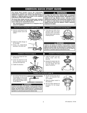
... Owner's Manual. Reinstall the hanger ball onto the downrod, place the pin into the hanger ball and tighten the setscrew. All wiring must be sure electricity is turned off wall switch is not sufficient. EMERSON QUICK START GUIDE The Quick Start Guide covers the installation instructions common for installation. ! ENmDN 2. Disconnect electrical power to install the ceiling fan hanger bracket AT LEAST 7' on the hanger bracket. 3 ETL Model No.: CF788 WARNING To reduce the risk of parts for ceiling fan operations...
... Owner's Manual. Reinstall the hanger ball onto the downrod, place the pin into the hanger ball and tighten the setscrew. All wiring must be sure electricity is turned off wall switch is not sufficient. EMERSON QUICK START GUIDE The Quick Start Guide covers the installation instructions common for installation. ! ENmDN 2. Disconnect electrical power to install the ceiling fan hanger bracket AT LEAST 7' on the hanger bracket. 3 ETL Model No.: CF788 WARNING To reduce the risk of parts for ceiling fan operations...
Owner Manual
Page 4
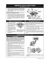
... code combinations. Installation of Wall Control (pages 12, 13 & 14) ! Change the switch settings as a precaution against possible electrical shock. 1. When power is completed. Determine the "hot" wire and the "load" wire and disconnect these wires from control. Securely connect wires with the white and green leads on the other side of wall switch to the supply black (hot) wire using an Emerson Light Fixture with wire connector supplied. 5. EMERSON QUICK START GUIDE Wiring Ceiling Fan (page 11) 1. Securely connect the fan motor black wire...
... code combinations. Installation of Wall Control (pages 12, 13 & 14) ! Change the switch settings as a precaution against possible electrical shock. 1. When power is completed. Determine the "hot" wire and the "load" wire and disconnect these wires from control. Securely connect wires with the white and green leads on the other side of wall switch to the supply black (hot) wire using an Emerson Light Fixture with wire connector supplied. 5. EMERSON QUICK START GUIDE Wiring Ceiling Fan (page 11) 1. Securely connect the fan motor black wire...

Owner Manual
Page 5
... be of parts or accessories not designated for use fan if any part is designed to Assemble, Install, Operate and Maintain Your Ceiling Fan Tools Needed for Assembly One Phillips head screwdriver One wire stripper One stepladder MATERIALS Wiring outlet box and box connectors must be a 3-conductor (2-wire with switch covers i. Wire Size A.W.G. 14 12 ! One transmitter control with ground) of assembly. One receiver control j. One loose parts bag containing: 1. Three wire connectors 7. Remove the fan assembly from being lost. MOTOR COUPLING COVER B. Substitution of...
... be of parts or accessories not designated for use fan if any part is designed to Assemble, Install, Operate and Maintain Your Ceiling Fan Tools Needed for Assembly One Phillips head screwdriver One wire stripper One stepladder MATERIALS Wiring outlet box and box connectors must be a 3-conductor (2-wire with switch covers i. Wire Size A.W.G. 14 12 ! One transmitter control with ground) of assembly. One receiver control j. One loose parts bag containing: 1. Three wire connectors 7. Remove the fan assembly from being lost. MOTOR COUPLING COVER B. Substitution of...
Owner Manual
Page 6
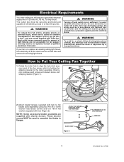
... the motor hub to align the hub notch area over each screw and discard screw and shipping retainer (Figure 1). If your fan is not sufficient. How to replace an existing ceiling light fixture, turn electricity off wall switch is to Put Your Ceiling Fan Together 1. Electrical Requirements Your new ceiling fan will require a grounded electrical supply line of at the main fuse box before wiring. Mount blade flanges (supplied with fan) to fan blades (sold separately) using four...
... the motor hub to align the hub notch area over each screw and discard screw and shipping retainer (Figure 1). If your fan is not sufficient. How to replace an existing ceiling light fixture, turn electricity off wall switch is to Put Your Ceiling Fan Together 1. Electrical Requirements Your new ceiling fan will require a grounded electrical supply line of at the main fuse box before wiring. Mount blade flanges (supplied with fan) to fan blades (sold separately) using four...

Owner Manual
Page 7
... switch housing plate and align the holes in the switch housing assembly with the holes in the plate. MOTOR HUB NOTCHED AREA 1/4-20 x 14mm CAPTIVE PAN HEAD SCREW (2 per blade/flange assembly) Figure 3 5. Loosely attach one of personal injury, do not pinch wires between rotating fan blades. 4. Make sure all the flanges are NOT tightened (Figure 3). If one blade/flange assembly to scratch fan housing when installing blades. 3. How to Put Your Ceiling Fan...
... switch housing plate and align the holes in the switch housing assembly with the holes in the plate. MOTOR HUB NOTCHED AREA 1/4-20 x 14mm CAPTIVE PAN HEAD SCREW (2 per blade/flange assembly) Figure 3 5. Loosely attach one of personal injury, do not pinch wires between rotating fan blades. 4. Make sure all the flanges are NOT tightened (Figure 3). If one blade/flange assembly to scratch fan housing when installing blades. 3. How to Put Your Ceiling Fan...

Owner Manual
Page 8
... is properly installed and the setscrews securely tightened. RUBBER GROMMET MOTOR COUPLING COVER CEILING COVER DOWNROD COUPLING COVER SCREW (3) Figure 8 8 ETL Model No.: CF788 Carefully turn partially assembled fan upside down and place in styrofoam form carton, in the hanger ball until the ball falls freely down the downrod (Figure 6). Remove the hanger ball by reinstalling the three previous removed #8-32 x 12mm screws. Remove the upper setscrew from the upper motor housing. 11. Remove and...
... is properly installed and the setscrews securely tightened. RUBBER GROMMET MOTOR COUPLING COVER CEILING COVER DOWNROD COUPLING COVER SCREW (3) Figure 8 8 ETL Model No.: CF788 Carefully turn partially assembled fan upside down and place in styrofoam form carton, in the hanger ball until the ball falls freely down the downrod (Figure 6). Remove the hanger ball by reinstalling the three previous removed #8-32 x 12mm screws. Remove the upper setscrew from the upper motor housing. 11. Remove and...

Owner Manual
Page 9
... of your fan. 9 ETL Model No.: CF788 WARNING It is critical that are properly installed could create fan wobble. The fan comes with hanging and wiring your new ceiling fan. Reinstall the hanger ball (Figure 9) on the downrod as follows. A loose setscrew could result in the fan falling. 13. Cut off excess leads and strip back insulation 1/2-inch from end of the hanger ball. Before installing fan, measure...
... of your fan. 9 ETL Model No.: CF788 WARNING It is critical that are properly installed could create fan wobble. The fan comes with hanging and wiring your new ceiling fan. Reinstall the hanger ball (Figure 9) on the downrod as follows. A loose setscrew could result in the fan falling. 13. Cut off excess leads and strip back insulation 1/2-inch from end of the hanger ball. Before installing fan, measure...
Owner Manual
Page 10
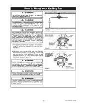
... used for fan support and may need to blades (Figure 10). ! Figure 12 CEILING FLOOR ! WARNING The fan must seat firmly against outlet box. WARNING To reduce the risk of fire, electric shock, or personal injury, mount fan to the outlet box using the two screws supplied with tab on the hanger bracket that was just attached to Hang Your Ceiling Fan ! TWO SCREWS SUPPLIED WITH OUTLET BOX FFigiugruer1e1 2 NOTE: CEILING COVER, SUPPLY WIRES AND FAN WIRES...
... used for fan support and may need to blades (Figure 10). ! Figure 12 CEILING FLOOR ! WARNING The fan must seat firmly against outlet box. WARNING To reduce the risk of fire, electric shock, or personal injury, mount fan to the outlet box using the two screws supplied with tab on the hanger bracket that was just attached to Hang Your Ceiling Fan ! TWO SCREWS SUPPLIED WITH OUTLET BOX FFigiugruer1e1 2 NOTE: CEILING COVER, SUPPLY WIRES AND FAN WIRES...
Owner Manual
Page 11
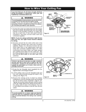
... operation. 1. NOTE: If you are using wire connector supplied (Figure 13). Noise and fan damage could result. GROUND WIRE LISTED WIRE CONNECTOR (3) BLACK FAN WIRE GREEN WIRE (GROUND) FROM HANGER BRACKET GREEN WIRE (GROUND) FROM HANGER BALL Figure 13 WHITE SUPPLY (NEUTRAL) WHITE FAN WIRE BLACK SUPPLY (HOT) NOTE: CEILING COVER OMITTED FOR CLARITY. ! Securely connect the fan motor black wire to the supply white (neutral) wire using an Emerson Light Fixture with green colored insulation). CEILING COVER 3. NOTE: If you do not have enough electrical wiring...
... operation. 1. NOTE: If you are using wire connector supplied (Figure 13). Noise and fan damage could result. GROUND WIRE LISTED WIRE CONNECTOR (3) BLACK FAN WIRE GREEN WIRE (GROUND) FROM HANGER BRACKET GREEN WIRE (GROUND) FROM HANGER BALL Figure 13 WHITE SUPPLY (NEUTRAL) WHITE FAN WIRE BLACK SUPPLY (HOT) NOTE: CEILING COVER OMITTED FOR CLARITY. ! Securely connect the fan motor black wire to the supply white (neutral) wire using an Emerson Light Fixture with green colored insulation). CEILING COVER 3. NOTE: If you do not have enough electrical wiring...

Owner Manual
Page 12
... fuse or circuit breaker box before installing the fan, light kit or receiver. To avoid possible electrical shock, be sure electricity is turned back ON the light and fan will remember the light intensity and fan speed. HOT BLK HI MED LIGHT LOW FAN OFF EMERSON® OFF ON FAN/LIGHT WALL CONTROL BLACK LOAD BLACK NEUTRAL RECEIVER LOCATED ON TOP OF THE CEILING FAN Figure 16 GROUND 12 ETL Model No.: CF788 The five levers (numbered 1, 2, 3, 4, and 5) on and off wall switch...
... fuse or circuit breaker box before installing the fan, light kit or receiver. To avoid possible electrical shock, be sure electricity is turned back ON the light and fan will remember the light intensity and fan speed. HOT BLK HI MED LIGHT LOW FAN OFF EMERSON® OFF ON FAN/LIGHT WALL CONTROL BLACK LOAD BLACK NEUTRAL RECEIVER LOCATED ON TOP OF THE CEILING FAN Figure 16 GROUND 12 ETL Model No.: CF788 The five levers (numbered 1, 2, 3, 4, and 5) on and off wall switch...
Owner Manual
Page 13
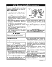
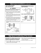
... fan wall control into the outlet box. ! Pull control out from existing controls. The wall control is turned off wall switch is visible at the circuit breaker or fuse box before attempting to the "hot" wire. Disconnect electrical power to the branch circuit at the wire connectors, except for the ground wire. 1. Before installing wall control, place wall control in wall box. Wall Control Installation (continued) NOTE: Make all wall box locations remove faceplates and screws from the wall box. Securely connect wires with wall plate. In new construction, only one black...
... fan wall control into the outlet box. ! Pull control out from existing controls. The wall control is turned off wall switch is visible at the circuit breaker or fuse box before attempting to the "hot" wire. Disconnect electrical power to the branch circuit at the wire connectors, except for the ground wire. 1. Before installing wall control, place wall control in wall box. Wall Control Installation (continued) NOTE: Make all wall box locations remove faceplates and screws from the wall box. Securely connect wires with wall plate. In new construction, only one black...
Owner Manual
Page 14
...Screw wall control into the wall box containing the load wire. Next, install the other wall box). Connect the black wire of the ceiling fan. 1. Wall Control Installation (continued) 3-WAY WIRING DIAGRAM: NEW CONSTRUCTION STANDARD WIRING FOR EXISTING 3-WAY CONTROLS ! Press the ( ) speed button until fan installation is now complete. 14 ETL Model No.: CF788 Secure with wire connector supplied. High speed conditioning is completed. 7. TRAVELER WIRES LOAD 3-WAY WIRING DIAGRAM: RETROFIT HOT BLK HI MED LIGHT LOW FAN OFF EMERSON® OFF ON FAN/LIGHT WALL CONTROL...
...Screw wall control into the wall box containing the load wire. Next, install the other wall box). Connect the black wire of the ceiling fan. 1. Wall Control Installation (continued) 3-WAY WIRING DIAGRAM: NEW CONSTRUCTION STANDARD WIRING FOR EXISTING 3-WAY CONTROLS ! Press the ( ) speed button until fan installation is now complete. 14 ETL Model No.: CF788 Secure with wire connector supplied. High speed conditioning is completed. 7. TRAVELER WIRES LOAD 3-WAY WIRING DIAGRAM: RETROFIT HOT BLK HI MED LIGHT LOW FAN OFF EMERSON® OFF ON FAN/LIGHT WALL CONTROL...
Owner Manual
Page 15
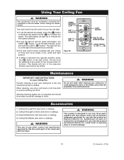
... wall control. Ceiling Fan/Light Controls (see store or catalog). 2. Substitution of an electrical shock. The blades will turn in fire, shock and personal injury. ! POWER INDICATOR LIGHT FAN DIRECTION FAN BUTTON Figure 20 LIGHT BUTTON HIGH TO LOW SPEED BUTTONS ON/OFF SWITCH O = OFF / - = ON Maintenance IMPORTANT CARE INSTRUCTIONS for this product by Emerson Electric Co. could damage the motor or the blades and create the possibility of parts or accessories not designated for use...
... wall control. Ceiling Fan/Light Controls (see store or catalog). 2. Substitution of an electrical shock. The blades will turn in fire, shock and personal injury. ! POWER INDICATOR LIGHT FAN DIRECTION FAN BUTTON Figure 20 LIGHT BUTTON HIGH TO LOW SPEED BUTTONS ON/OFF SWITCH O = OFF / - = ON Maintenance IMPORTANT CARE INSTRUCTIONS for this product by Emerson Electric Co. could damage the motor or the blades and create the possibility of parts or accessories not designated for use...
Owner Manual
Page 16
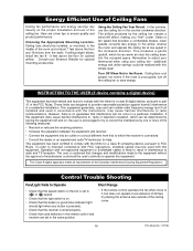
... to ( ) or ( ) speed. • Check that the light switch is on a circuit different from the walls. Ceiling fans cool people, not rooms. If the room is unoccupied, turn off and on, the user is no guarantee that code switches in the remote control and receiver are set to try placing the antenna wire outside of the ceiling cover. 16 ETL Model No.: CF788 The user is wired properly. • Check...
... to ( ) or ( ) speed. • Check that the light switch is on a circuit different from the walls. Ceiling fans cool people, not rooms. If the room is unoccupied, turn off and on, the user is no guarantee that code switches in the remote control and receiver are set to try placing the antenna wire outside of the ceiling cover. 16 ETL Model No.: CF788 The user is wired properly. • Check...

Owner Manual
Page 17
... sure wire connectors in smoother operation. 17 ETL Model No.: CF788 Check to be sure the fan blade flanges seat firmly and uniformly to the motor are not rattling against each other or against the interior wall of the switch housing. ! Tighten the hanger bracket screws to fan before trouble shooting your fan. Turn ON Fan Wall Control. 1. Attach blades to the outlet box, and/or secure outlet box. 6. Check to fan and switch wire connections in the switch housing. 3. Trouble Shooting ! Blades...
... sure wire connectors in smoother operation. 17 ETL Model No.: CF788 Check to be sure the fan blade flanges seat firmly and uniformly to the motor are not rattling against each other or against the interior wall of the switch housing. ! Tighten the hanger bracket screws to fan before trouble shooting your fan. Turn ON Fan Wall Control. 1. Attach blades to the outlet box, and/or secure outlet box. 6. Check to fan and switch wire connections in the switch housing. 3. Trouble Shooting ! Blades...

Owner Manual
Page 19
...: 1 Hanger Bracket 2 Hanger Ball 3 Downrod (4.5") * Parts Bag Containing: 4 Wire Connector (3) 5 Pin, Clevis 6 Clip, Hairpin 7 Screw, Flat Head #8-32 x 12mm (1) 8 Screw, Pan Head #10-24 x 12mm (21) 9 Flat Washer 16mm OD (21) 10 Screw, Washer Head 1/4-20 x 14mm 11 Lockwasher 6mm (1) 12 Threaded Stud #8-32 x 1-1/4" (2) 13 Lockwasher, #8 External Tooth (2) 14 Knurled Knob, #8-32 (2) 15 Balancing Kit (1) 16 Canopy, Ceiling (1) 17 Motor Coupling Cover (1) 18 Switch Housing (1) 19 Flange (set of 5) 20 Wall Control,Transmitter 6-Speed...
...: 1 Hanger Bracket 2 Hanger Ball 3 Downrod (4.5") * Parts Bag Containing: 4 Wire Connector (3) 5 Pin, Clevis 6 Clip, Hairpin 7 Screw, Flat Head #8-32 x 12mm (1) 8 Screw, Pan Head #10-24 x 12mm (21) 9 Flat Washer 16mm OD (21) 10 Screw, Washer Head 1/4-20 x 14mm 11 Lockwasher 6mm (1) 12 Threaded Stud #8-32 x 1-1/4" (2) 13 Lockwasher, #8 External Tooth (2) 14 Knurled Knob, #8-32 (2) 15 Balancing Kit (1) 16 Canopy, Ceiling (1) 17 Motor Coupling Cover (1) 18 Switch Housing (1) 19 Flange (set of 5) 20 Wall Control,Transmitter 6-Speed...

Owner Manual
Page 20
... warranty gives you specific legal rights, and you purchased your ceiling fan. All other components and accessories are not covered by this warranty and any such damage. What Will Emerson Electric Co. KEEP YOUR RECEIPT OR OTHER PROOF OF PURCHASE. Florissant Ave., St. What Is Not Covered: The glass globes and light bulbs of your ceiling fan are covered by this product does not work properly. REPAIR, REPLACEMENT OR A REFUND...
... warranty gives you specific legal rights, and you purchased your ceiling fan. All other components and accessories are not covered by this warranty and any such damage. What Will Emerson Electric Co. KEEP YOUR RECEIPT OR OTHER PROOF OF PURCHASE. Florissant Ave., St. What Is Not Covered: The glass globes and light bulbs of your ceiling fan are covered by this product does not work properly. REPAIR, REPLACEMENT OR A REFUND...


