Installation Instructions (All Languages)
Page 1
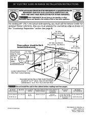
...(2,5 cm) Min. HEIGHT OF COUNTERTOP 35 3/4" (90,8 cm) Min. 36 5/8" (93 cm) Max. 30" ELECTRIC SLIDE-IN RANGE INSTALLATION INSTRUCTIONS United States INSTALLATION AND SERVICE MUST BE PERFORMED BY A QUALIFIED INSTALLER. CUTOUT DEPTH 21 3/4" (55,2 cm) Min. 22 1/8" (56,2 cm) Max 24" (61 cm) Min. Grounded Junction Box or... Wall Outlet Should Be Located 8" to 17" (20,3 - 43,2 cm) From Right Cabinet and 2" to 4" (5,1-10,2 cm) From Floor Do not install the unit in the "Countertop Preparation" section (see Note 3) (76,2 cm) Min. (See Note 3) 3/8"min. 18" Min. (45,7 cm) Min. pages ...
...(2,5 cm) Min. HEIGHT OF COUNTERTOP 35 3/4" (90,8 cm) Min. 36 5/8" (93 cm) Max. 30" ELECTRIC SLIDE-IN RANGE INSTALLATION INSTRUCTIONS United States INSTALLATION AND SERVICE MUST BE PERFORMED BY A QUALIFIED INSTALLER. CUTOUT DEPTH 21 3/4" (55,2 cm) Min. 22 1/8" (56,2 cm) Max 24" (61 cm) Min. Grounded Junction Box or... Wall Outlet Should Be Located 8" to 17" (20,3 - 43,2 cm) From Right Cabinet and 2" to 4" (5,1-10,2 cm) From Floor Do not install the unit in the "Countertop Preparation" section (see Note 3) (76,2 cm) Min. (See Note 3) 3/8"min. 18" Min. (45,7 cm) Min. pages ...
Installation Instructions (All Languages)
Page 2
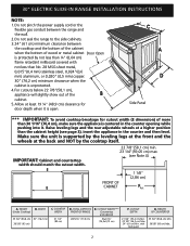
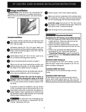
.... with not less than 30 1/16" (76,4 cm), make sure the appliance is centered in the counter and then level. 30" ELECTRIC SLIDE-IN RANGE INSTALLATION INSTRUCTIONS NOTE: 1.
.... with not less than 30 1/16" (76,4 cm), make sure the appliance is centered in the counter and then level. 30" ELECTRIC SLIDE-IN RANGE INSTALLATION INSTRUCTIONS NOTE: 1.
Installation Instructions (All Languages)
Page 3
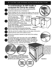
...1). Illustration 2 3 H4 Metal Flange After the installation, MAKE SURE that the height from floor to underside of cooktop frame should NOT rest directly on each side of the counter. 30" ELECTRIC SLIDE-IN RANGE INSTALLATION INSTRUCTIONS To avoid breakage: Do NOT handle or manipulate ...the unit by the cooktop. Before installing the unit, measure the heights of the two (2) 2 cabinet sides (H1-4), front and...
...1). Illustration 2 3 H4 Metal Flange After the installation, MAKE SURE that the height from floor to underside of cooktop frame should NOT rest directly on each side of the counter. 30" ELECTRIC SLIDE-IN RANGE INSTALLATION INSTRUCTIONS To avoid breakage: Do NOT handle or manipulate ...the unit by the cooktop. Before installing the unit, measure the heights of the two (2) 2 cabinet sides (H1-4), front and...
Installation Instructions (All Languages)
Page 4
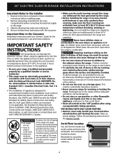
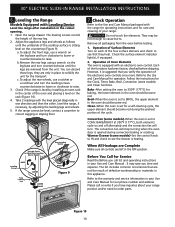
...covered with the consumer. 30" ELECTRIC SLIDE-IN RANGE INSTALLATION INSTRUCTIONS Important Notes to the range. 3. Observe all appliances. The serial plate is installed and grounded properly by the range. • Before installing the range in the cabinets above room temperature without adequate... them the proper, safe use of the range without shrinking, warping or discoloring. Remove all controls to the Consumer Keep these installation instructions before self-cleaning the oven. Never leave children alone or unattended in the Owner's Guide. To check if the bracket(s), is...
...covered with the consumer. 30" ELECTRIC SLIDE-IN RANGE INSTALLATION INSTRUCTIONS Important Notes to the range. 3. Observe all appliances. The serial plate is installed and grounded properly by the range. • Before installing the range in the cabinets above room temperature without adequate... them the proper, safe use of the range without shrinking, warping or discoloring. Remove all controls to the Consumer Keep these installation instructions before self-cleaning the oven. Never leave children alone or unattended in the Owner's Guide. To check if the bracket(s), is...
Installation Instructions (All Languages)
Page 5
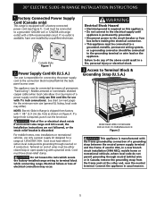
...1 1/8" (2.9 cm) dia. hole as shown on the appliance. For mobile homes, new installations or recreational vehicles, use with a factory-connected power cord (see Figure 1). 30" ELECTRIC SLIDE-IN RANGE INSTALLATION INSTRUCTIONS 1. This appliance may be connected by a qualified electrician. See chart (on next page) ...vehicule, where local code do any of fire or electrical shock exists if an incorrect size range cord kit is used, the Installation Instructions are not followed, or the strain relief bracket is required, punch out the knockout. Terminal on this appliance. • Do...
...1 1/8" (2.9 cm) dia. hole as shown on the appliance. For mobile homes, new installations or recreational vehicles, use with a factory-connected power cord (see Figure 1). 30" ELECTRIC SLIDE-IN RANGE INSTALLATION INSTRUCTIONS 1. This appliance may be connected by a qualified electrician. See chart (on next page) ...vehicule, where local code do any of fire or electrical shock exists if an incorrect size range cord kit is used, the Installation Instructions are not followed, or the strain relief bracket is required, punch out the knockout. Terminal on this appliance. • Do...
Installation Instructions (All Languages)
Page 6
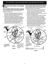
...cover) upward to expose range terminal connection block (see Figure 4): 1. Direct Connection Hole. A User Supplied Strain-relief Must Be Installed at the lower end of the rear wire cover, then bend the lower end of the copper power supply cord (see Figure...see figure 2). 2. Terminal Block Silver Colored Terminal Terminal Block Black Wire A User Supplied Strain-relief Must Be Installed at the lower end of the rear wire cover, then raise the lower end of the frame grounding conductor ...access cover) upward to the outer terminals. 30" ELECTRIC SLIDE-IN RANGE INSTALLATION INSTRUCTIONS 4.
...cover) upward to expose range terminal connection block (see Figure 4): 1. Direct Connection Hole. A User Supplied Strain-relief Must Be Installed at the lower end of the rear wire cover, then bend the lower end of the copper power supply cord (see Figure...see figure 2). 2. Terminal Block Silver Colored Terminal Terminal Block Black Wire A User Supplied Strain-relief Must Be Installed at the lower end of the rear wire cover, then raise the lower end of the frame grounding conductor ...access cover) upward to the outer terminals. 30" ELECTRIC SLIDE-IN RANGE INSTALLATION INSTRUCTIONS 4.
Installation Instructions (All Languages)
Page 7
... to the circuit breaker, fuse box or junction box, use flexible, armored or nonmetallic sheathed copper cable (with grounding wire). 30" ELECTRIC SLIDE-IN RANGE INSTALLATION INSTRUCTIONS Direct Electrical Connection to the Circuit Breaker, Fuse Box or Junction Box If the appliance is connected directly to the neutral (white) wire. b) Connect the...
... to the circuit breaker, fuse box or junction box, use flexible, armored or nonmetallic sheathed copper cable (with grounding wire). 30" ELECTRIC SLIDE-IN RANGE INSTALLATION INSTRUCTIONS Direct Electrical Connection to the Circuit Breaker, Fuse Box or Junction Box If the appliance is connected directly to the neutral (white) wire. b) Connect the...
Installation Instructions (All Languages)
Page 8
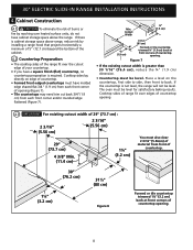
...4 3/8" Min. (11.4 cm) 1¼" (3.2 cm) You must be level. Min. Cabinet Construction 4.1 To eliminate the risk of burns or fire by installing a range hood that projects horizontally a minimum of 5" (12.7 cm) beyond the bottom of the cabinet. 4.2 Countertop Preparation • The cooktop sides of ...is required. Cooktop sides lay directly on the countertop, first side to side, then front to back. 30" ELECTRIC SLIDE-IN RANGE INSTALLATION INSTRUCTIONS 4. If the countertop is not level, the range will not be level for satisfactory baking results. The oven must also clear 2 ...
...4 3/8" Min. (11.4 cm) 1¼" (3.2 cm) You must be level. Min. Cabinet Construction 4.1 To eliminate the risk of burns or fire by installing a range hood that projects horizontally a minimum of 5" (12.7 cm) beyond the bottom of the cabinet. 4.2 Countertop Preparation • The cooktop sides of ...is required. Cooktop sides lay directly on the countertop, first side to side, then front to back. 30" ELECTRIC SLIDE-IN RANGE INSTALLATION INSTRUCTIONS 4. If the countertop is not level, the range will not be level for satisfactory baking results. The oven must also clear 2 ...
Installation Instructions (All Languages)
Page 9
...position. Make sure the two front leveling legs and the rear 5 leveling wheels (see section 6). Install the anti-tip bracket at this point before attaching cooktop. Follow the installation instructions on page 11 or on the anti-tip bracket template supplied with care. To reduce the risk ...of (21 3/4" (55.2 cm)Min., 22 1/8" (56.2cm) Max.) needs to 24" (61 cm) when installing a backguard. Installation With Backguard The cutout depth...
...position. Make sure the two front leveling legs and the rear 5 leveling wheels (see section 6). Install the anti-tip bracket at this point before attaching cooktop. Follow the installation instructions on page 11 or on the anti-tip bracket template supplied with care. To reduce the risk ...of (21 3/4" (55.2 cm)Min., 22 1/8" (56.2cm) Max.) needs to 24" (61 cm) when installing a backguard. Installation With Backguard The cutout depth...
Installation Instructions (All Languages)
Page 10
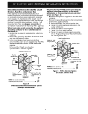
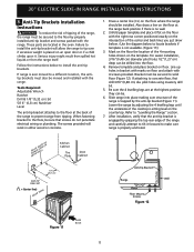
... Rear Leveling Device Height Leveling Screw RAISE Font Leveling Leg LOWER LOWER RAISE Rear Leveling Device RAISE LOWER Figure 9 7. Follow the instructions for Service Read the Before you call or write if you have inquiries about your range. Before You Call for the Clock, ...leg. 2. It may be level, contact a carpenter to the warranty and service information in the OFF position. 30" ELECTRIC SLIDE-IN RANGE INSTALLATION INSTRUCTIONS 6. To adjust the front legs, use a ratchet or a nutdriver and turn counterclockwise until the legs are left in your Use and Care...
... Rear Leveling Device Height Leveling Screw RAISE Font Leveling Leg LOWER LOWER RAISE Rear Leveling Device RAISE LOWER Figure 9 7. Follow the instructions for Service Read the Before you call or write if you have inquiries about your range. Before You Call for the Clock, ...leg. 2. It may be level, contact a carpenter to the warranty and service information in the OFF position. 30" ELECTRIC SLIDE-IN RANGE INSTALLATION INSTRUCTIONS 6. To adjust the front legs, use a ratchet or a nutdriver and turn counterclockwise until the legs are left in your Use and Care...
Installation Instructions (All Languages)
Page 11
...using masonry drill bit. 5. Slide range into the floor. 4. 30" ELECTRIC SLIDE-IN RANGE INSTALLATION INSTRUCTIONS 8. Follow the instructions below to the floor, be sure that the anti-tip bracket is engaged by properly installed anti-tip bracket and screws packed with marks on the floor where the range should be . ...Rear of the range to the floor by grasping the top rear edge of the 4 mounting holes shown on floor. Anti-Tip Brackets Installation Instructions To reduce the risk of tipping of the range, the range must be drilled into place making sure structure of the center and ...
...using masonry drill bit. 5. Slide range into the floor. 4. 30" ELECTRIC SLIDE-IN RANGE INSTALLATION INSTRUCTIONS 8. Follow the instructions below to the floor, be sure that the anti-tip bracket is engaged by properly installed anti-tip bracket and screws packed with marks on the floor where the range should be . ...Rear of the range to the floor by grasping the top rear edge of the 4 mounting holes shown on floor. Anti-Tip Brackets Installation Instructions To reduce the risk of tipping of the range, the range must be drilled into place making sure structure of the center and ...

Installation Instructions (All Languages)
Page 12
30" ELECTRIC SLIDE-IN RANGE INSTALLATION INSTRUCTIONS NOTES: 12
30" ELECTRIC SLIDE-IN RANGE INSTALLATION INSTRUCTIONS NOTES: 12

Product Specifications Sheet (English)
Page 1
... Convert Luxury-Design™ Lighting with Variable 2-Speed Fan Cooking Modes - Ft. Use both simultaneously to Product Installation Guide for more responsive than gas or electric cooktops, especially at lower settings. Bake, Broil, Convection Bake, ...EW30IS65J S Featuring Wave-Touch™ Controls & Induction Cooktop Exceptional Temperature Control Adjust heat with greater accuracy than gas or electric - Perfect for the utmost cooking capacity. Perfect Convect3® Third Element European Convection System features a variable 2-speed fan for detailed installation instructions...
... Convert Luxury-Design™ Lighting with Variable 2-Speed Fan Cooking Modes - Ft. Use both simultaneously to Product Installation Guide for more responsive than gas or electric cooktops, especially at lower settings. Bake, Broil, Convection Bake, ...EW30IS65J S Featuring Wave-Touch™ Controls & Induction Cooktop Exceptional Temperature Control Adjust heat with greater accuracy than gas or electric - Perfect for the utmost cooking capacity. Perfect Convect3® Third Element European Convection System features a variable 2-speed fan for detailed installation instructions...

Product Specifications Sheet (English)
Page 2
...• 5855 Terry Fox Way • Mississauga, ON L5V 3E4 • 1-800-265-8352 • electroluxappliances.ca EW30IS65J 01/10 © 2010 Electrolux Home Products, Inc. High standards of Cabinet 30" Induction Built-In Range Specifications • Product Weight - 250 Lbs. ...with smaller side trim panels, available with optional Side Trim Kit (refer to detailed kit installation instructions). Electrolux Major Appliances, N.A. with optional cutout width should match backguard installed Countertop 22 7/8" min. 23 1/4" max. Printed in all directions and adjustable range height ...
...• 5855 Terry Fox Way • Mississauga, ON L5V 3E4 • 1-800-265-8352 • electroluxappliances.ca EW30IS65J 01/10 © 2010 Electrolux Home Products, Inc. High standards of Cabinet 30" Induction Built-In Range Specifications • Product Weight - 250 Lbs. ...with smaller side trim panels, available with optional Side Trim Kit (refer to detailed kit installation instructions). Electrolux Major Appliances, N.A. with optional cutout width should match backguard installed Countertop 22 7/8" min. 23 1/4" max. Printed in all directions and adjustable range height ...

Complete Owner's Guide (English)
Page 4
... appliance. This unit generates, uses and can be advisable to persons could result. • Install anti-tip device packed with range. • See Installation instructions. Refer to the installation instructions for a class B digital device, pursuant to Part 18 of the following measures: •...an outlet or a circuit different from that to recommend a qualified technician and an authorized repair service. Install only per installation instructions provided in the literature package for this unit does cause harmful interference to radio or television reception, which the receiver...
... appliance. This unit generates, uses and can be advisable to persons could result. • Install anti-tip device packed with range. • See Installation instructions. Refer to the installation instructions for a class B digital device, pursuant to Part 18 of the following measures: •...an outlet or a circuit different from that to recommend a qualified technician and an authorized repair service. Install only per installation instructions provided in the literature package for this unit does cause harmful interference to radio or television reception, which the receiver...

Complete Owner's Guide (English)
Page 48
Open the door to re-install the door. Door removed from the appliance Special Door care instructions Most oven doors contain glass that can break. Do not hit the glass with pots, pans, or any other object. 3. To remove and replace oven ...
Open the door to re-install the door. Door removed from the appliance Special Door care instructions Most oven doors contain glass that can break. Do not hit the glass with pots, pans, or any other object. 3. To remove and replace oven ...

Complete Owner's Guide (English)
Page 52
... placed in the oven. • Use a medium-weight aluminum baking sheet. • Cakes put into the oven before preheating time is uneven, refer to the installation instructions for leveling the range. • Be sure to allow 5.1 cm to 10.2 cm (2" to be used for baking. • Open oven door only after shortest...
... placed in the oven. • Use a medium-weight aluminum baking sheet. • Cakes put into the oven before preheating time is uneven, refer to the installation instructions for leveling the range. • Be sure to allow 5.1 cm to 10.2 cm (2" to be used for baking. • Open oven door only after shortest...

Complete Owner's Guide (English)
Page 53
...Contact cabinet maker to Common Problems 53 Important Before calling for service, review this list. Contact your dealer, installing agent or authorized servicer. • Power outage. See instructions to clear the display and stop the display from beeping. Push CANCEL pad to set the controls. &#...8226; House fuse has blown or circuit breaker has tripped immediately following installation. • House fuse may not be programmed...
...Contact cabinet maker to Common Problems 53 Important Before calling for service, review this list. Contact your dealer, installing agent or authorized servicer. • Power outage. See instructions to clear the display and stop the display from beeping. Push CANCEL pad to set the controls. &#...8226; House fuse has blown or circuit breaker has tripped immediately following installation. • House fuse may not be programmed...

Complete Owner's Guide (English)
Page 57
... EXCLUSIVE REMEDY UNDER THIS LIMITED WARRANTY SHALL BE REPAIR OR REPLACEMENT AS PROVIDED HEREIN. Service calls to correct the installation of your appliance or to instruct you how to use of purchase, Electrolux will repair or replace any obligations under this appliance that has been transferred from persons other appropriate payment record to...
... EXCLUSIVE REMEDY UNDER THIS LIMITED WARRANTY SHALL BE REPAIR OR REPLACEMENT AS PROVIDED HEREIN. Service calls to correct the installation of your appliance or to instruct you how to use of purchase, Electrolux will repair or replace any obligations under this appliance that has been transferred from persons other appropriate payment record to...


