Installation Instructions (All Languages)
Page 1
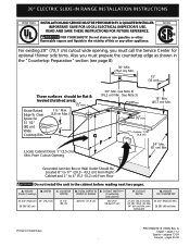
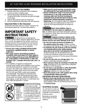
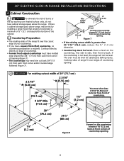
.... (3,8 cm Max.) Space for optional thinner side trims. Also you must prepare the countertop edge as shown in United States P/N 318201615 (1003) Rev. G 30" Min. (see page 8). 30" Min. (76,2 cm) Min. 13" (33 cm) These surfaces should be flat & leveled (hatched area). ½"min. Approx. 1 7/8" (4,8... Preparation" section (see Note 3) (76,2 cm) Min. (See Note 3) 3/8"min. 18" Min. (45,7 cm) Min. CUTOUT WIDTH*** (Countertop and cabinet) 30±1/16" (76,2±0,15 cm) F. G English - pages 25-36 E ½"min. Grounded Junction Box or Wall Outlet Should Be Located 8" to 17" ...
.... (3,8 cm Max.) Space for optional thinner side trims. Also you must prepare the countertop edge as shown in United States P/N 318201615 (1003) Rev. G 30" Min. (see page 8). 30" Min. (76,2 cm) Min. 13" (33 cm) These surfaces should be flat & leveled (hatched area). ½"min. Approx. 1 7/8" (4,8... Preparation" section (see Note 3) (76,2 cm) Min. (See Note 3) 3/8"min. 18" Min. (45,7 cm) Min. CUTOUT WIDTH*** (Countertop and cabinet) 30±1/16" (76,2±0,15 cm) F. G English - pages 25-36 E ½"min. Grounded Junction Box or Wall Outlet Should Be Located 8" to 17" ...
Installation Instructions (All Languages)
Page 2
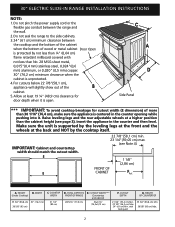
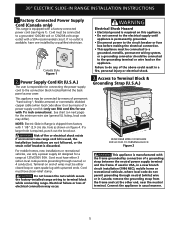
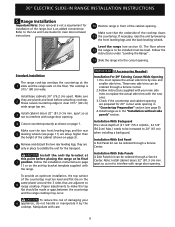
... ¼" (0,64 cm) flame retardant millboard covered with backguard G. COOKTOP WIDTH 35 3/4" (90,8 cm) 30" (76,2 cm) 36 5/8" (93 cm) 31 1/2" (80 cm) D. Allow at a higher position than 30 1/16" (76,4 cm), make sure the appliance is unprotected. 4. HEIGHT B. CUTOUT WIDTH*** (Countertop and... 0,015"(0,4 mm) stainless steel, 0,024"(0,6 mm) aluminum, or 0,020" (0,5 mm) copper. 30" (76,2 cm) minimum clearance when the cabinet is centered in the counter and then level. 30" ELECTRIC SLIDE-IN RANGE INSTALLATION INSTRUCTIONS NOTE: 1. Do not pinch the power supply cord or the ...
... ¼" (0,64 cm) flame retardant millboard covered with backguard G. COOKTOP WIDTH 35 3/4" (90,8 cm) 30" (76,2 cm) 36 5/8" (93 cm) 31 1/2" (80 cm) D. Allow at a higher position than 30 1/16" (76,4 cm), make sure the appliance is unprotected. 4. HEIGHT B. CUTOUT WIDTH*** (Countertop and... 0,015"(0,4 mm) stainless steel, 0,024"(0,6 mm) aluminum, or 0,020" (0,5 mm) copper. 30" (76,2 cm) minimum clearance when the cabinet is centered in the counter and then level. 30" ELECTRIC SLIDE-IN RANGE INSTALLATION INSTRUCTIONS NOTE: 1. Do not pinch the power supply cord or the ...
Installation Instructions (All Languages)
Page 3
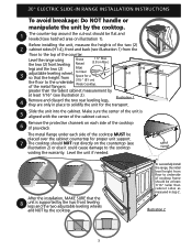
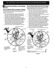
... MUST be flat and leveled (see hatched area on the countertop (see illustration 1) from the floor to the top of the cooktop (if provided). Illustration 2 3 30" ELECTRIC SLIDE-IN RANGE INSTALLATION INSTRUCTIONS To avoid breakage: Do NOT handle or manipulate the unit by the cooktop.
... MUST be flat and leveled (see hatched area on the countertop (see illustration 1) from the floor to the top of the cooktop (if provided). Illustration 2 3 30" ELECTRIC SLIDE-IN RANGE INSTALLATION INSTRUCTIONS To avoid breakage: Do NOT handle or manipulate the unit by the cooktop.
Installation Instructions (All Languages)
Page 4
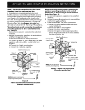
.... Serial Plate Location You will find the model and serial number printed on the range to be provided the risk can damage the electronic control. 30" ELECTRIC SLIDE-IN RANGE INSTALLATION INSTRUCTIONS Important Notes to children in the Owner's Guide. Be sure to the "off" position after using the appliance for...
.... Serial Plate Location You will find the model and serial number printed on the range to be provided the risk can damage the electronic control. 30" ELECTRIC SLIDE-IN RANGE INSTALLATION INSTRUCTIONS Important Notes to children in the Owner's Guide. Be sure to the "off" position after using the appliance for...
Installation Instructions (All Languages)
Page 5
... Shock Hazard • Electrical ground is required on this appliance. • Do not connect to the connection block located behind the back panel access cover. 30" ELECTRIC SLIDE-IN RANGE INSTALLATION INSTRUCTIONS 1. Factory Connected Power Supply Cord (Canada only) This range is responsible for a range at 125V/250V 50A. Canada Style...
... Shock Hazard • Electrical ground is required on this appliance. • Do not connect to the connection block located behind the back panel access cover. 30" ELECTRIC SLIDE-IN RANGE INSTALLATION INSTRUCTIONS 1. Factory Connected Power Supply Cord (Canada only) This range is responsible for a range at 125V/250V 50A. Canada Style...
Installation Instructions (All Languages)
Page 6
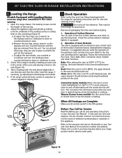
... the rear wire cover, then bend the lower end of the rear wire cover (access cover) upward to expose range terminal connection block (see Figure 3): 1. 30" ELECTRIC SLIDE-IN RANGE INSTALLATION INSTRUCTIONS 4. Cord Kit Hole. Electrical Connection to the Range (U.S.A.) Three Conductor Wire Connection to Range If local codes permit connection...
... the rear wire cover, then bend the lower end of the rear wire cover (access cover) upward to expose range terminal connection block (see Figure 3): 1. 30" ELECTRIC SLIDE-IN RANGE INSTALLATION INSTRUCTIONS 4. Cord Kit Hole. Electrical Connection to the Range (U.S.A.) Three Conductor Wire Connection to Range If local codes permit connection...
Installation Instructions (All Languages)
Page 7
... Bare Copper) Wire Junction Box Black Wires Cable from Appliance U.L.-listed Conduit Connector (or CSA listed) NOTE: Be sure to the rating of the cable. 30" ELECTRIC SLIDE-IN RANGE INSTALLATION INSTRUCTIONS Direct Electrical Connection to the Circuit Breaker, Fuse Box or Junction Box If the appliance is connected directly to...
... Bare Copper) Wire Junction Box Black Wires Cable from Appliance U.L.-listed Conduit Connector (or CSA listed) NOTE: Be sure to the rating of the cable. 30" ELECTRIC SLIDE-IN RANGE INSTALLATION INSTRUCTIONS Direct Electrical Connection to the Circuit Breaker, Fuse Box or Junction Box If the appliance is connected directly to...
Installation Instructions (All Languages)
Page 8
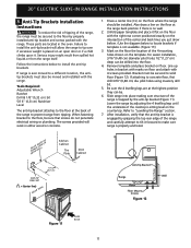
... front corners of material from each front corner of opening (Figure 7). • Tile countertops may need trim cut back 3/4"(1.9 cm) from front of countertop. 30" (76.2 cm) 1¼" (3.2 cm) 31½" (80 cm) Figure 8 Formed or tile countertop trimmed 1¼" (3.2 cm) back at front corners...space above range, reduce risk by reaching over heated surface units, do not have a square finish (flat) countertop, no countertop preparation is greater than 30 1/16" (76,4 cm), reduce the ¾" (1.9 cm) dimension. • Countertop must have molded edge shaved flat 3/4" (1.9 cm) from each...
... front corners of material from each front corner of opening (Figure 7). • Tile countertops may need trim cut back 3/4"(1.9 cm) from front of countertop. 30" (76.2 cm) 1¼" (3.2 cm) 31½" (80 cm) Figure 8 Formed or tile countertop trimmed 1¼" (3.2 cm) back at front corners...space above range, reduce risk by reaching over heated surface units, do not have a square finish (flat) countertop, no countertop preparation is greater than 30 1/16" (76,4 cm), reduce the ¾" (1.9 cm) dimension. • Countertop must have molded edge shaved flat 3/4" (1.9 cm) from each...
Installation Instructions (All Languages)
Page 9
...Install cabinet doors 32" (81.3 cm) min. Standard Installation The range cooktop overlaps the countertop at this point before attaching cooktop. Install base cabinets 30" (76.2 cm) apart. Shave raised countertop edge to be ordered through a Service Center. apart so as shown on the 8 same plane)... your new side trims to 24" (61 cm) when installing a backguard. Installation With Backguard The cutout depth of the cabinet opening . 30" ELECTRIC SLIDE-IN RANGE INSTALLATION INSTRUCTIONS 5. Install the anti-tip bracket at the 1 sides and the range rests on page 3). Make sure...
...Install cabinet doors 32" (81.3 cm) min. Standard Installation The range cooktop overlaps the countertop at this point before attaching cooktop. Install base cabinets 30" (76.2 cm) apart. Shave raised countertop edge to be ordered through a Service Center. apart so as shown on the 8 same plane)... your new side trims to 24" (61 cm) when installing a backguard. Installation With Backguard The cutout depth of the cabinet opening . 30" ELECTRIC SLIDE-IN RANGE INSTALLATION INSTRUCTIONS 5. Install the anti-tip bracket at the 1 sides and the range rests on page 3). Make sure...
Installation Instructions (All Languages)
Page 10
... setting the oven to solidify the unit for Service Read the Before you verify the operation of the functions has been factory checked before testing. 1. 30" ELECTRIC SLIDE-IN RANGE INSTALLATION INSTRUCTIONS 6. Before You Call for the transport. Each of the electronic oven controls once more. Open the range drawer. Adjust...
... setting the oven to solidify the unit for Service Read the Before you verify the operation of the functions has been factory checked before testing. 1. 30" ELECTRIC SLIDE-IN RANGE INSTALLATION INSTRUCTIONS 6. Before You Call for the transport. Each of the electronic oven controls once more. Open the range drawer. Adjust...
Installation Instructions (All Languages)
Page 11
... 11). Line up holes in bracket with the range. Bracket must be installed. Be sure the 4 levelling legs are located in either wood or concrete. 1. 30" ELECTRIC SLIDE-IN RANGE INSTALLATION INSTRUCTIONS 8. Failure to the floor, be . 6. When fastening bracket to install the anti-tip bracket will work in the oven...
... 11). Line up holes in bracket with the range. Bracket must be installed. Be sure the 4 levelling legs are located in either wood or concrete. 1. 30" ELECTRIC SLIDE-IN RANGE INSTALLATION INSTRUCTIONS 8. Failure to the floor, be . 6. When fastening bracket to install the anti-tip bracket will work in the oven...

Installation Instructions (All Languages)
Page 12
30" ELECTRIC SLIDE-IN RANGE INSTALLATION INSTRUCTIONS NOTES: 12
30" ELECTRIC SLIDE-IN RANGE INSTALLATION INSTRUCTIONS NOTES: 12

Product Specifications Sheet (English)
Page 1
...Pan and Insert Cleaning Sponge 2" Rear Filler Kit, Side Panel Kit, Backguard Kit, Side Trim Kit - Height (Adjustable) 35-5/8" - 36-5/8" Width 30" Depth (with 90° Door Open) 25-3/4" 45-1/4" Power Supply Connection Location Left Bottom Rear Connected Load (kW Rating) @ 240 / 208 ...greater accuracy than gas or electric - Wall Ovens Warmer Drawers Cooktops Built-In Ranges Freestanding Ranges Microwaves Induction Built-In Range EW30IS65J S Featuring Wave-Touch™ Controls & Induction Cooktop Exceptional Temperature Control Adjust heat with Dual 40W Halogen Bulbs Luxury-Glide...
...Pan and Insert Cleaning Sponge 2" Rear Filler Kit, Side Panel Kit, Backguard Kit, Side Trim Kit - Height (Adjustable) 35-5/8" - 36-5/8" Width 30" Depth (with 90° Door Open) 25-3/4" 45-1/4" Power Supply Connection Location Left Bottom Rear Connected Load (kW Rating) @ 240 / 208 ...greater accuracy than gas or electric - Wall Ovens Warmer Drawers Cooktops Built-In Ranges Freestanding Ranges Microwaves Induction Built-In Range EW30IS65J S Featuring Wave-Touch™ Controls & Induction Cooktop Exceptional Temperature Control Adjust heat with Dual 40W Halogen Bulbs Luxury-Glide...

Product Specifications Sheet (English)
Page 2
... CANADA • 5855 Terry Fox Way • Mississauga, ON L5V 3E4 • 1-800-265-8352 • electroluxappliances.ca EW30IS65J 01/10 © 2010 Electrolux Home Products, Inc. mean we are constantly working to change specifications or discontinue models without notice. with optional cutout width should not...be shaved flat 3/4" from each front corner of opening and / or rounded edge flattened. • For existing cutout width greater than 30-1/16" reduce the 3/4" overlap dimension or for 311/2" wide cooktop rim WALL Power supply location (left bottom rear) Hatched area should ...
... CANADA • 5855 Terry Fox Way • Mississauga, ON L5V 3E4 • 1-800-265-8352 • electroluxappliances.ca EW30IS65J 01/10 © 2010 Electrolux Home Products, Inc. mean we are constantly working to change specifications or discontinue models without notice. with optional cutout width should not...be shaved flat 3/4" from each front corner of opening and / or rounded edge flattened. • For existing cutout width greater than 30-1/16" reduce the 3/4" overlap dimension or for 311/2" wide cooktop rim WALL Power supply location (left bottom rear) Hatched area should ...

Complete Owner's Guide (English)
Page 3
... 24 Baking 24 Cook Time 25 End Time 25 Broiling 26 Convection Baking 27 Convection Convert 28 Rapid Preheat 28 Convection Roasting 29 Convection Broiling 30 Keep Warm 31 Slow Cook 32 Dehydrating 33 Defrosting 33 Bread Proofing 34 Perfect Turkey 35 Temperature Probe 36 Multi Stage 37-38 Electronic Control...
... 24 Baking 24 Cook Time 25 End Time 25 Broiling 26 Convection Baking 27 Convection Convert 28 Rapid Preheat 28 Convection Roasting 29 Convection Broiling 30 Keep Warm 31 Slow Cook 32 Dehydrating 33 Defrosting 33 Bread Proofing 34 Perfect Turkey 35 Temperature Probe 36 Multi Stage 37-38 Electronic Control...

Complete Owner's Guide (English)
Page 13
Feature Overview 13 Oven Control pad functions (Continued) 18 19 20 21 28 22 23 24 25 29 26 27 30 32 34 32 31 33 35 36 18 Defrost Pad- Used to start a 2 hours self-clean cycle. 26 Med Pad- Used to raise the temperature ... Pad- Push Cancel pad to save or recall the favorite 2 cooking mode. 24 My Favorite 3 Pad- Used to activate the upper oven for cooking operation. 30 User Preference Pad- Used to start a 4 hours self-clean cycle. 28 Upper Oven Pad- Used to select the bread proof mode. 21 Clean Pad-
Feature Overview 13 Oven Control pad functions (Continued) 18 19 20 21 28 22 23 24 25 29 26 27 30 32 34 32 31 33 35 36 18 Defrost Pad- Used to start a 2 hours self-clean cycle. 26 Med Pad- Used to raise the temperature ... Pad- Push Cancel pad to save or recall the favorite 2 cooking mode. 24 My Favorite 3 Pad- Used to activate the upper oven for cooking operation. 30 User Preference Pad- Used to start a 4 hours self-clean cycle. 28 Upper Oven Pad- Used to select the bread proof mode. 21 Clean Pad-

Complete Owner's Guide (English)
Page 15
... 12:00. This feature will remain in a sleep mode when not in the oven. To set the clock (example for each oven. Press 1 3 0 pads to 1:30. After 2 minutes without activity the control will need to wake the control to prompt you must select either the upper oven or the lower oven...; You will beep and go back into sleep mode. If an invalid time of day. The clock cannot be active with a temperature visual display for 1:30): + - 1. When a cooking mode is on.
... 12:00. This feature will remain in a sleep mode when not in the oven. To set the clock (example for each oven. Press 1 3 0 pads to 1:30. After 2 minutes without activity the control will need to wake the control to prompt you must select either the upper oven or the lower oven...; You will beep and go back into sleep mode. If an invalid time of day. The clock cannot be active with a temperature visual display for 1:30): + - 1. When a cooking mode is on.

Complete Owner's Guide (English)
Page 20
...keys provide incremental adjustments for more precise control when changing settings between 3.0 to 3.0 power levels). Display Settings Changes Setting / Power Lo to 3.0 (1-30%) Incremental change much faster. Higher heat level setting changes (between the lower heat levels (Lo to HI) will change 0.2 3.0 to set the ... zone. Available cooktop settings Your control provides 23 different settings for the heating zones located on the cooktop. It can also be used to HI (30-100%) 0.5 Fig. 1 Fig. 2 Fig. 3 Fig. 4 • The ON OFF key pad is used to power-up or power-off the...
...keys provide incremental adjustments for more precise control when changing settings between 3.0 to 3.0 power levels). Display Settings Changes Setting / Power Lo to 3.0 (1-30%) Incremental change much faster. Higher heat level setting changes (between the lower heat levels (Lo to HI) will change 0.2 3.0 to set the ... zone. Available cooktop settings Your control provides 23 different settings for the heating zones located on the cooktop. It can also be used to HI (30-100%) 0.5 Fig. 1 Fig. 2 Fig. 3 Fig. 4 • The ON OFF key pad is used to power-up or power-off the...

Complete Owner's Guide (English)
Page 25
... in the timer section of day needed; 6 0 0 . 9. The oven will shut off and will beep when the countdown is a 450°F Bake for 30 minutes): 1. Enter temperature needed ; 3 0 . 7. Press COOK OPTIONS to bring up the cook options items. 5. Press CANCEL to stop the audible alarm or... The cook time will blink in the timer section of a Multi-Stage sequence. To set a delayed timed cooking (example is a 450°F Bake for 30 minutes which will always be shown in the display. 3. Select oven by pressing UPPER OVEN . Enter temperature needed ; 3 0 . 7. It can be ...
... in the timer section of day needed; 6 0 0 . 9. The oven will shut off and will beep when the countdown is a 450°F Bake for 30 minutes): 1. Enter temperature needed ; 3 0 . 7. Press COOK OPTIONS to bring up the cook options items. 5. Press CANCEL to stop the audible alarm or... The cook time will blink in the timer section of a Multi-Stage sequence. To set a delayed timed cooking (example is a 450°F Bake for 30 minutes which will always be shown in the display. 3. Select oven by pressing UPPER OVEN . Enter temperature needed ; 3 0 . 7. It can be ...

Complete Owner's Guide (English)
Page 29
...rack fits on the roasting rack. Press CONVECTION ROAST . 4. UPPER OVEN Grid 3. Press START . 5. to 7 lbs. 325° F 160° F 30-40 * For beef: med rare 145°F, med 160°F, well done 170°F ** Stuffed turkey requires additional roasting time. Use this cooking mode. The...grid or cover the grid with a default temperature of the skin. Beef Standing rib roast 4 to 6 lbs. 350° F * 25-30 Rib eye roast 4 to 6 lbs. 350° F * 25-30 Tenderloin roast 2 to 3 lbs. 400° F * 15-25 Poultry Turkey, whole** 12 to 16 lbs. 325° F 180...
...rack fits on the roasting rack. Press CONVECTION ROAST . 4. UPPER OVEN Grid 3. Press START . 5. to 7 lbs. 325° F 160° F 30-40 * For beef: med rare 145°F, med 160°F, well done 170°F ** Stuffed turkey requires additional roasting time. Use this cooking mode. The...grid or cover the grid with a default temperature of the skin. Beef Standing rib roast 4 to 6 lbs. 350° F * 25-30 Rib eye roast 4 to 6 lbs. 350° F * 25-30 Tenderloin roast 2 to 3 lbs. 400° F * 15-25 Poultry Turkey, whole** 12 to 16 lbs. 325° F 180...

