User Manual
Page 2
User Guide EVGA nForce 780i SLI Motherboard
User Guide EVGA nForce 780i SLI Motherboard
User Manual
Page 4
... the Kit ix Intentions of the Kit x EVGA nForce 780i Motherboard 1 Motherboard Specifications 1 Unpacking and Parts Descriptions 4 Unpacking ...4 Equipment ...4 EVGA nForce 780i SLI Motherboard 5 Hardware Installation ...9 Safety Instructions...9 Preparing the Motherboard 10 Installing the CPU 10 Installing the CPU Fan 11 Installing Memory DIMMs 11 Installing the Motherboard 12 Installing the I/O Shield 12 Securing the Motherboard into the Chassis 13 Connecting Cables and...
... the Kit ix Intentions of the Kit x EVGA nForce 780i Motherboard 1 Motherboard Specifications 1 Unpacking and Parts Descriptions 4 Unpacking ...4 Equipment ...4 EVGA nForce 780i SLI Motherboard 5 Hardware Installation ...9 Safety Instructions...9 Preparing the Motherboard 10 Installing the CPU 10 Installing the CPU Fan 11 Installing Memory DIMMs 11 Installing the Motherboard 12 Installing the I/O Shield 12 Securing the Motherboard into the Chassis 13 Connecting Cables and...

User Manual
Page 5
780i 3-Way SLI Motherboard Connecting Serial ATA Cables 18 Connecting Internal Headers 19 Front Panel Header 19 IEEE 1394a ...20 USB Headers 21 Audio ...22 Fan Connections 23 COM1 ...24 FDD Connector 25 Expansion Slots 25 PCI Slots ...25 PCI Express x1 Slot 26 PCI Express x16 Slots 26 Jumper Settings ...27 Clear CMOS Jumper: CLR_CMOS 27 Configuring the BIOS 29 Enter BIOS Setup 30 Main Menu...30 Standard CMOS Features Menu 33 Date and Time...34 IDE Channel and SATA Channel 34 Drive A...37 Halt On ...37 Memory ...38 Advanced BIOS Features 39 Removable Device Priority 40 EVGA iv
780i 3-Way SLI Motherboard Connecting Serial ATA Cables 18 Connecting Internal Headers 19 Front Panel Header 19 IEEE 1394a ...20 USB Headers 21 Audio ...22 Fan Connections 23 COM1 ...24 FDD Connector 25 Expansion Slots 25 PCI Slots ...25 PCI Express x1 Slot 26 PCI Express x16 Slots 26 Jumper Settings ...27 Clear CMOS Jumper: CLR_CMOS 27 Configuring the BIOS 29 Enter BIOS Setup 30 Main Menu...30 Standard CMOS Features Menu 33 Date and Time...34 IDE Channel and SATA Channel 34 Drive A...37 Halt On ...37 Memory ...38 Advanced BIOS Features 39 Removable Device Priority 40 EVGA iv
User Manual
Page 6
nForce 780i SLI Motherboard Hard Disk Boot Priority 40 Network Boot Priority 40 CPU Internal Cache 40 Quick Power On Self Test 41 First/Second/Third Boot Device 41 ...
nForce 780i SLI Motherboard Hard Disk Boot Priority 40 Network Boot Priority 40 CPU Internal Cache 40 Quick Power On Self Test 41 First/Second/Third Boot Device 41 ...
User Manual
Page 7
780i 3-Way SLI Motherboard IEEE1394 controller 62 HD Audio ...62 IDE HDD Block Mode 62 Onboard FDC Controller 62 Onboard Serial Port 1 63 Power Management Setup Menu 63 ACPI ... 70 Installing Drivers and Software 72 Driver Installation 73 Using the NVIDIA Software 74 NVIDIA Performance Group of NVIDIA Control Panel 75 Device Settings 76 EVGA vi
780i 3-Way SLI Motherboard IEEE1394 controller 62 HD Audio ...62 IDE HDD Block Mode 62 Onboard FDC Controller 62 Onboard Serial Port 1 63 Power Management Setup Menu 63 ACPI ... 70 Installing Drivers and Software 72 Driver Installation 73 Using the NVIDIA Software 74 NVIDIA Performance Group of NVIDIA Control Panel 75 Device Settings 76 EVGA vi
User Manual
Page 8
Configuring an SLI Configuration 104 SLI Connector ...104 ForceWare Driver 105 Enabling 3-Way SLI 107 Verifying 3-way SLI is Active 109 Index...110 nForce 780i SLI Motherboard Current Hardware Settings 77 Dynamic BIOS Access 84 View System Information 85 Profile Policies...86 Manage Your System BIOS 87 NVIDIA System Monitor 88 Appendix A. POST Codes for Tritium Platform 94 Appendix B.
Configuring an SLI Configuration 104 SLI Connector ...104 ForceWare Driver 105 Enabling 3-Way SLI 107 Verifying 3-way SLI is Active 109 Index...110 nForce 780i SLI Motherboard Current Hardware Settings 77 Dynamic BIOS Access 84 View System Information 85 Profile Policies...86 Manage Your System BIOS 87 NVIDIA System Monitor 88 Appendix A. POST Codes for Tritium Platform 94 Appendix B.
User Manual
Page 10
... Supply The power supply requirement is dependent upon the power and the number of a 350 W power supply. As you go to require for your new EVGA nForce® 780i SLI motherboard. These instructions tell you how to SLI two graphics cards, you will need a minimum of a 500 W power supply. If you have three GPUs in an... install each of the parts listed so you will need a minimum of the GPUs you are going to www.slizone.com. If you have a functioning motherboard. nForce 780i SLI Motherboard Before You Begin...
... Supply The power supply requirement is dependent upon the power and the number of a 350 W power supply. As you go to require for your new EVGA nForce® 780i SLI motherboard. These instructions tell you how to SLI two graphics cards, you will need a minimum of a 500 W power supply. If you have three GPUs in an... install each of the parts listed so you will need a minimum of the GPUs you are going to www.slizone.com. If you have a functioning motherboard. nForce 780i SLI Motherboard Before You Begin...

User Manual
Page 11
If however, you are building a PC, you will use most of the Kit This kit provides you with the motherboard and all connecting cables necessary to reinstall an operating system even though the current drives have an operating system. When replacing a motherboard in the kit. EVGA x If you are replacing a motherboard, you will need many of the cables. 780i 3-Way SLI Motherboard Intentions of the cables provided in a PC case, you will not need to install the motherboard into a PC case.
If however, you are building a PC, you will use most of the Kit This kit provides you with the motherboard and all connecting cables necessary to reinstall an operating system even though the current drives have an operating system. When replacing a motherboard in the kit. EVGA x If you are replacing a motherboard, you will need many of the cables. 780i 3-Way SLI Motherboard Intentions of the cables provided in a PC case, you will not need to install the motherboard into a PC case.
User Manual
Page 12
EVGA nForce 780i Motherboard Thank you get innovative NVIDIA SLI Technology for buying the EVGA NFORCE 780i SLI Motherboard. Supports up to 8 GBs of 12 inch x 9.6 inch ‰ Microprocessor support Intel Core 2 Extreme, Intel Core 2 Quad, Intel Core 2 Duo, Pentium EE, Pentium D, Pentium ‰ Operating systems: Supports Windows XP 32bit/64bit and Windows Vista 32bit/64bit ‰ Contains NVIDIA nForce 780i SLI MCP and...
EVGA nForce 780i Motherboard Thank you get innovative NVIDIA SLI Technology for buying the EVGA NFORCE 780i SLI Motherboard. Supports up to 8 GBs of 12 inch x 9.6 inch ‰ Microprocessor support Intel Core 2 Extreme, Intel Core 2 Quad, Intel Core 2 Duo, Pentium EE, Pentium D, Pentium ‰ Operating systems: Supports Windows XP 32bit/64bit and Windows Vista 32bit/64bit ‰ Contains NVIDIA nForce 780i SLI MCP and...
User Manual
Page 13
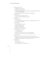
off) ‰ Expansion Slots ¾ Two PCI slots ¾ One PCI Express x1 slot ¾ Three PCI Express x16 Graphics slots 780i 3-Way SLI Motherboard EVGA 2 ‰ Onboard Serial ATA II ¾ 300MBps data transfer rate ¾ Six Serial ATA II connectors ¾ NVIDIA MediaShield RAID with support for RAID 0, RAID 1, ...
off) ‰ Expansion Slots ¾ Two PCI slots ¾ One PCI Express x1 slot ¾ Three PCI Express x16 Graphics slots 780i 3-Way SLI Motherboard EVGA 2 ‰ Onboard Serial ATA II ¾ 300MBps data transfer rate ¾ Six Serial ATA II connectors ¾ NVIDIA MediaShield RAID with support for RAID 0, RAID 1, ...

User Manual
Page 14
nForce 780i SLI Motherboard
nForce 780i SLI Motherboard

User Manual
Page 15
... The following equipment is included in the EVGA nForce 780i SLI motherboard box. (Accessories may not need many of equipment shipped in the chassis to the motherboard. 4 I/O Shield Installs in the packing box. If you may vary between models, see product package) EVGA nForce 780i SLI Motherboard This PCI Express motherboard contains the NVIDIA nForce 780i SLI SPP and MCP and is missing or damaged...
... The following equipment is included in the EVGA nForce 780i SLI motherboard box. (Accessories may not need many of equipment shipped in the chassis to the motherboard. 4 I/O Shield Installs in the packing box. If you may vary between models, see product package) EVGA nForce 780i SLI Motherboard This PCI Express motherboard contains the NVIDIA nForce 780i SLI SPP and MCP and is missing or damaged...

User Manual
Page 16
... the chassis. nForce 780i SLI Motherboard 2-Port SATA Power Cable (Qty Three) 1394 Cable Provides two additional 1394 ports to either the front or back panels of the chassis. USB 2.0 4-Port Cable Provides four additional USB ports to the motherboard Comm2 Bracket Cable IDE-ATA 133 HDD Cable EVGA nForce 780i SLI Motherboard The EVGA nForce 780i SLI motherboard with the NVIDIA nForce 780i SLI SPP and MCP...
... the chassis. nForce 780i SLI Motherboard 2-Port SATA Power Cable (Qty Three) 1394 Cable Provides two additional 1394 ports to either the front or back panels of the chassis. USB 2.0 4-Port Cable Provides four additional USB ports to the motherboard Comm2 Bracket Cable IDE-ATA 133 HDD Cable EVGA nForce 780i SLI Motherboard The EVGA nForce 780i SLI motherboard with the NVIDIA nForce 780i SLI SPP and MCP...

User Manual
Page 17
... headers 12. Serial connector 15. CPU fan connector 4. Fan connector 14. Serial-ATA (SATA) connectors 8. PCI Express x16 slots (SLI) 24. 1394a connector 25. 780i 3-Way SLI Motherboard 22 22 25 23 24 23 23 21 20 19 26 27 28 29 1187 13 1 13 2 16 3 15 4 14...Connector 7. SPDIF connector 22. PCI Express x1 slot 26. Motherboard battery 13. DDR DIMM Slots 0 - 3 5. 24-pin ATX Power Connector 6. NVIDIA SPP with Active fan 3. Heat dissipater 28. 8-pin ATX_12V power connector 29 MCP/SPP fan connector EVGA 6 Reset Button 19. Power button 18. PCI slots ...
... headers 12. Serial connector 15. CPU fan connector 4. Fan connector 14. Serial-ATA (SATA) connectors 8. PCI Express x16 slots (SLI) 24. 1394a connector 25. 780i 3-Way SLI Motherboard 22 22 25 23 24 23 23 21 20 19 26 27 28 29 1187 13 1 13 2 16 3 15 4 14...Connector 7. SPDIF connector 22. PCI Express x1 slot 26. Motherboard battery 13. DDR DIMM Slots 0 - 3 5. 24-pin ATX Power Connector 6. NVIDIA SPP with Active fan 3. Heat dissipater 28. 8-pin ATX_12V power connector 29 MCP/SPP fan connector EVGA 6 Reset Button 19. Power button 18. PCI slots ...

User Manual
Page 18
nForce 780i SLI Motherboard 10. Serial-ATA (SATA) connectors 20. SPDIF output 6. Lan Port with LEDs to indicate status. • Yellow/Light Up/Blink = 10 Mbps/Link/Activity • ... 4-Channel Line-In Front Speaker Out Mic In Rear Speaker Out 6-Channel/8-Channel Line-In Front Speaker Out Mic In Center/Subwoofer Rear Speaker Out 7. EVGA nForce 780i SLI Motherboard Layout 7 7 1 2 3 4 5 6 4 4 1. USB 2.0 ports (SIX) 5. FP Audio connector Figure 1. PS/2 Keyboard Port 3. 1394a (Firewire) Port 4. Chassis Backpanel Connectors...
nForce 780i SLI Motherboard 10. Serial-ATA (SATA) connectors 20. SPDIF output 6. Lan Port with LEDs to indicate status. • Yellow/Light Up/Blink = 10 Mbps/Link/Activity • ... 4-Channel Line-In Front Speaker Out Mic In Rear Speaker Out 6-Channel/8-Channel Line-In Front Speaker Out Mic In Center/Subwoofer Rear Speaker Out 7. EVGA nForce 780i SLI Motherboard Layout 7 7 1 2 3 4 5 6 4 4 1. USB 2.0 ports (SIX) 5. FP Audio connector Figure 1. PS/2 Keyboard Port 3. 1394a (Firewire) Port 4. Chassis Backpanel Connectors...

User Manual
Page 19
780i 3-Way SLI Motherboard EVGA 8
780i 3-Way SLI Motherboard EVGA 8
User Manual
Page 21
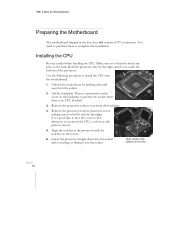
You need to purchase these to install the CPU onto the motherboard. 1. There is a protective socket cover on the load plate to protect the socket when there is a good idea to save the cover so that whenever ... its protective cover, making sure you have a safe place to bend or break any pins on the back. 780i 3-Way SLI Motherboard Preparing the Motherboard The motherboard shipped in the processor with notches on the CPU EVGA 10 Lower the processor straight down and away from the socket. 2. Unhook the socket lever by pushing down into...
You need to purchase these to install the CPU onto the motherboard. 1. There is a protective socket cover on the load plate to protect the socket when there is a good idea to save the cover so that whenever ... its protective cover, making sure you have a safe place to bend or break any pins on the back. 780i 3-Way SLI Motherboard Preparing the Motherboard The motherboard shipped in the processor with notches on the CPU EVGA 10 Lower the processor straight down and away from the socket. 2. Unhook the socket lever by pushing down into...
User Manual
Page 23
...an empty chassis. Align the memory module to the DIMM slot, and insert the module vertically into the chassis depends on the covers. EVGA 12 780i 3-Way SLI Motherboard Use the following procedure to install the I /O shield into place and make sure it would need to obtain the proper size from dust... the chassis you are using and if you would be easier to make all the connections prior to this step or to secure the motherboard and then make sure the CPU Fan assembly is normally easier to block radio frequency transmissions, protects internal components from the chassis supplier. ...
...an empty chassis. Align the memory module to the DIMM slot, and insert the module vertically into the chassis depends on the covers. EVGA 12 780i 3-Way SLI Motherboard Use the following procedure to install the I /O shield into place and make sure it would need to obtain the proper size from dust... the chassis you are using and if you would be easier to make all the connections prior to this step or to secure the motherboard and then make sure the CPU Fan assembly is normally easier to block radio frequency transmissions, protects internal components from the chassis supplier. ...

User Manual
Page 25
... 3): ¾ Four 6-pin (3x2) and two 8-pin (4x2) PCI-E power connectors or ¾ Six 6-pin (3x2) PCI-E power connectors EVGA 14 8-pin (4x2) PCT-E Connector 6-pin (3x2) PCI-E connector Figure 3. 780i 3-Way SLI Motherboard ‰ IDE ‰ Serial ATA II ‰ Chassis Fans ‰ Rear panel USB 2.0 Adapter ‰ Expansion slots ‰ CMOS jumper...
... 3): ¾ Four 6-pin (3x2) and two 8-pin (4x2) PCI-E power connectors or ¾ Six 6-pin (3x2) PCI-E power connectors EVGA 14 8-pin (4x2) PCT-E Connector 6-pin (3x2) PCI-E connector Figure 3. 780i 3-Way SLI Motherboard ‰ IDE ‰ Serial ATA II ‰ Chassis Fans ‰ Rear panel USB 2.0 Adapter ‰ Expansion slots ‰ CMOS jumper...

User Manual
Page 27
Connect the blue connector (the cable end with the two closely spaced black and gray connectors) to the motherboard. 2. Connect the black connector (the cable with a single connector) to the Ultra ATA master device. 3. If you install two hard disk drives,...accordingly. EVGA 16 Align the pins to a slave device. Connect the gray connector to the connector and press firmly until seated. Backpanel connector 5 1 12V GND 8 4 Connecting IDE Hard Disk Drives The IDE connector supports Ultra ATA 133/100/66 IDE hard disk drives. 1. Refer to the CPU. 780i 3-Way SLI Motherboard 8-...
Connect the blue connector (the cable end with the two closely spaced black and gray connectors) to the motherboard. 2. Connect the black connector (the cable with a single connector) to the Ultra ATA master device. 3. If you install two hard disk drives,...accordingly. EVGA 16 Align the pins to a slave device. Connect the gray connector to the connector and press firmly until seated. Backpanel connector 5 1 12V GND 8 4 Connecting IDE Hard Disk Drives The IDE connector supports Ultra ATA 133/100/66 IDE hard disk drives. 1. Refer to the CPU. 780i 3-Way SLI Motherboard 8-...
