
User Manual
Page 24
... the Chassis Most computer chassis have a base with the studs/spacers. 3. Align the connectors to the fan assembly instruction. 5. Secure the motherboard with a minimum of a short circuit. This will include: ‰ Power Connections ¾ 24-pin ATX power (PWR1) ¾ 8-pin ATX 12V power (PWR2) ... USB Headers ¾ Audio ¾ Speaker ¾ COM ‰ FDD Align the mounting holes with mounting studs or spacers to allow the mother board to be secured to the chassis and help to prevent short circuits. Connecting Cables and Setting Switches This section takes you remove that do not...
... the Chassis Most computer chassis have a base with the studs/spacers. 3. Align the connectors to the fan assembly instruction. 5. Secure the motherboard with a minimum of a short circuit. This will include: ‰ Power Connections ¾ 24-pin ATX power (PWR1) ¾ 8-pin ATX 12V power (PWR2) ... USB Headers ¾ Audio ¾ Speaker ¾ COM ‰ FDD Align the mounting holes with mounting studs or spacers to allow the mother board to be secured to the chassis and help to prevent short circuits. Connecting Cables and Setting Switches This section takes you remove that do not...
User Manual
Page 26
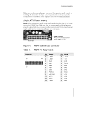
... Installation Make sure you have enough power to PWR1 Figure 4. Board edge PWR1 connector Plug power cable from system power supply to cover all the expansion cards you power requirements are properly aligned with the connector on the motherboard. Table 1. PWR1 Motherboard Connector PWR1 Pin Assignments Connector 24 12 Pin Signal 1 13 ...the power supply cable into the connector and make sure it is the main power supply connector located along the edge of the board next to www.slizone.com. 24-pin ATX Power (PWR1) PWR1 is secure. To determine what you will be installing.
... Installation Make sure you have enough power to PWR1 Figure 4. Board edge PWR1 connector Plug power cable from system power supply to cover all the expansion cards you power requirements are properly aligned with the connector on the motherboard. Table 1. PWR1 Motherboard Connector PWR1 Pin Assignments Connector 24 12 Pin Signal 1 13 ...the power supply cable into the connector and make sure it is the main power supply connector located along the edge of the board next to www.slizone.com. 24-pin ATX Power (PWR1) PWR1 is secure. To determine what you will be installing.

User Manual
Page 38
...2 together using the jumper cap. 2. Return the jumper setting to be cleared by removing the CMOS jumper. Hardware Installation Jumper Settings The motherboard contains a 3-pin BIOS configuration jumper that enables all the set parameters. The CMOS can be done in the BIOS Setup program. Clear ...CMOS Jumper: CLR_CMOS The motherboard uses the CMOS RAM to clear CMOS: 1. Turn the AC power supply back on the motherboard shows a ∆ next to pin 1. Use the following procedure to store all board configurations to normal (pins 2 and 3 together with the...
...2 together using the jumper cap. 2. Return the jumper setting to be cleared by removing the CMOS jumper. Hardware Installation Jumper Settings The motherboard contains a 3-pin BIOS configuration jumper that enables all the set parameters. The CMOS can be done in the BIOS Setup program. Clear ...CMOS Jumper: CLR_CMOS The motherboard uses the CMOS RAM to clear CMOS: 1. Turn the AC power supply back on the motherboard shows a ∆ next to pin 1. Use the following procedure to store all board configurations to normal (pins 2 and 3 together with the...

User Manual
Page 86
... component. Without ever leaving Windows or entering the BIOS, users can save these settings as a profile by using the Profile menu item. NVIDIA and the board manufacturer are not responsible for damage that may void its warranty due to the rest of the components within NVIDIA Performance Group are dynamically applied...
... component. Without ever leaving Windows or entering the BIOS, users can save these settings as a profile by using the Profile menu item. NVIDIA and the board manufacturer are not responsible for damage that may void its warranty due to the rest of the components within NVIDIA Performance Group are dynamically applied...

User Manual
Page 88
At all times, real-time values for damage that may void its warranty due to dynamically change FSB speeds, CPU Voltages, and CPU fan speeds. NVIDIA and the board manufacturer are not responsible for CPU frequency and appropriate CPU multiplier are exceeded. CAUTION: Increasing the voltage or the clock speed of a component may occur when component tolerances are reported. Using NVIDIA Software Current Hardware Settings CPU This option deals with CPU parameters and information. Here, the user has the ability to exceeding recommended specifications.
At all times, real-time values for damage that may void its warranty due to dynamically change FSB speeds, CPU Voltages, and CPU fan speeds. NVIDIA and the board manufacturer are not responsible for CPU frequency and appropriate CPU multiplier are exceeded. CAUTION: Increasing the voltage or the clock speed of a component may occur when component tolerances are reported. Using NVIDIA Software Current Hardware Settings CPU This option deals with CPU parameters and information. Here, the user has the ability to exceeding recommended specifications.

User Manual
Page 111
To program chipset from defaults values E1- EVGA 100 Read/Write CPU registers Base memory detect Board Initialization Turn on extended memory, cache initialization First display initialization Early shadow enable for last micro details before boot Set ...NumLock status according to disable NMI, F2 reboot. Page 1, E2 - If unmasked NMI occurs, display Press F1 to Setup Set low stack Boot via INT 19h. 780i 3-Way SLI Motherboard...
To program chipset from defaults values E1- EVGA 100 Read/Write CPU registers Base memory detect Board Initialization Turn on extended memory, cache initialization First display initialization Early shadow enable for last micro details before boot Set ...NumLock status according to disable NMI, F2 reboot. Page 1, E2 - If unmasked NMI occurs, display Press F1 to Setup Set low stack Boot via INT 19h. 780i 3-Way SLI Motherboard...
