
User Manual
Page 22
They also support dual channel DDR2 memory technology up to ensure normal operation. The idea is fully seated and level in adjacent slots. ‰ Four DIMMS: Install into slot 0. Follow the instruction that came with this motherboard. CPU side DIMM Slot 0 DIMM Slot 2 Card-edge DIMM Slot... 1 DIMM Slot 3 Use the following the recommendations for installing memory. (See Figure 1 on page 7 for DDR2 memory. These slots support 256 MB, 512 MB, 1 GB, and 2...
They also support dual channel DDR2 memory technology up to ensure normal operation. The idea is fully seated and level in adjacent slots. ‰ Four DIMMS: Install into slot 0. Follow the instruction that came with this motherboard. CPU side DIMM Slot 0 DIMM Slot 2 Card-edge DIMM Slot... 1 DIMM Slot 3 Use the following the recommendations for installing memory. (See Figure 1 on page 7 for DDR2 memory. These slots support 256 MB, 512 MB, 1 GB, and 2...

User Manual
Page 27
... with the two closely spaced black and gray connectors) to the hard disk documentation for the jumper settings. Connect the gray connector to the motherboard. 2. Connect the black connector (the cable with a single connector) to a slave device. If you install two hard disk drives, you...device. 3. Backpanel connector 5 1 12V GND 8 4 Connecting IDE Hard Disk Drives The IDE connector supports Ultra ATA 133/100/66 IDE hard disk drives. 1. EVGA 16 Align the pins to the CPU. 780i 3-Way SLI Motherboard 8-pin ATX 12V Power (PWR2) PWR2, the 8-pin ATX 12V power connection, is used to ...
... with the two closely spaced black and gray connectors) to the hard disk documentation for the jumper settings. Connect the gray connector to the motherboard. 2. Connect the black connector (the cable with a single connector) to a slave device. If you install two hard disk drives, you...device. 3. Backpanel connector 5 1 12V GND 8 4 Connecting IDE Hard Disk Drives The IDE connector supports Ultra ATA 133/100/66 IDE hard disk drives. 1. EVGA 16 Align the pins to the CPU. 780i 3-Way SLI Motherboard 8-pin ATX 12V Power (PWR2) PWR2, the 8-pin ATX 12V power connection, is used to ...

User Manual
Page 64
... Enhanced Halt State Execute Disable Bit Virtualization Technology [Disabled] Disabled [Disabled] [Enabled] [Enabled] [Enabled] CPU Core 0 CPU Core 1 x CPU Core 2 x CPU Core 3 Enabled [Enabled] Disabled Disabled Item Help Main Level `` Set linit CPUID MaxVal to enable or disable TM1 and TM2 support. Options are Auto, 7.8uS, and 3.9uS). Set to Disable for Win XP. ‰...
... Enhanced Halt State Execute Disable Bit Virtualization Technology [Disabled] Disabled [Disabled] [Enabled] [Enabled] [Enabled] CPU Core 0 CPU Core 1 x CPU Core 2 x CPU Core 3 Enabled [Enabled] Disabled Disabled Item Help Main Level `` Set linit CPUID MaxVal to enable or disable TM1 and TM2 support. Options are Auto, 7.8uS, and 3.9uS). Set to Disable for Win XP. ‰...

User Manual
Page 65
780i 3-Way SLI Motherboard ¾ TM1 Only The CPU is thermally throttled by cutting active processor clock cycles. ¾ TM2 Only Thermal throttling is achieved by Intel Virtualization Technology. ‰ CPU Core 1 This function allows you to enable or disable CPU Core. EVGA 54 Idle occurs when the... Virtualization Technology When this function reduces the CPU power consumption when the CPU is enabled, it allows a VMM to utilize the additional hardware capabilities provided by reducing the CPU multiplier and CPU core voltage. ¾ TM1 & TM2 Enables support for both TM1 and TM2. ‰...
780i 3-Way SLI Motherboard ¾ TM1 Only The CPU is thermally throttled by cutting active processor clock cycles. ¾ TM2 Only Thermal throttling is achieved by Intel Virtualization Technology. ‰ CPU Core 1 This function allows you to enable or disable CPU Core. EVGA 54 Idle occurs when the... Virtualization Technology When this function reduces the CPU power consumption when the CPU is enabled, it allows a VMM to utilize the additional hardware capabilities provided by reducing the CPU multiplier and CPU core voltage. ¾ TM1 & TM2 Enables support for both TM1 and TM2. ‰...
User Manual
Page 113
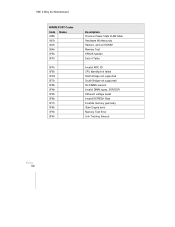
780i 3-Way SLI Motherboard NVMM POST Codes Code Name 048h 04Ch 050h 054h 0FEh 0FFh 0FFh 0FEh 0FDh 0FCh 0FBh 0FAh 0F9h 0F8h 0F7h 0F6h 0F5h 0F4h Description Previous Power State SLAM table Hardware Workarounds Restore, and exit NVMM Memory Test ERROR handler End of Table Invalid APIC ID CPU Identify/Init failed North Bridge not supported South Bridge not supported No DIMMs present Invalid DIMM types, SDR/DDR Different voltage levels Invalid REFRESH Rate Invalide memory geometry Slam Engine error Memory Test Error Link Training timeout EVGA 102
780i 3-Way SLI Motherboard NVMM POST Codes Code Name 048h 04Ch 050h 054h 0FEh 0FFh 0FFh 0FEh 0FDh 0FCh 0FBh 0FAh 0F9h 0F8h 0F7h 0F6h 0F5h 0F4h Description Previous Power State SLAM table Hardware Workarounds Restore, and exit NVMM Memory Test ERROR handler End of Table Invalid APIC ID CPU Identify/Init failed North Bridge not supported South Bridge not supported No DIMMs present Invalid DIMM types, SDR/DDR Different voltage levels Invalid REFRESH Rate Invalide memory geometry Slam Engine error Memory Test Error Link Training timeout EVGA 102
