
User Manual
Page 18
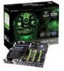
... Rear Speaker Out 7. SPDIF output 6. Serial-ATA (SATA) connectors 20. FP Audio connector Figure 1. EVGA nForce 780i SLI Motherboard Layout 7 7 1 2 3 4 5 6 4 4 1. Lan Port with LEDs to indicate status. • Yellow/Light Up/Blink = 10 Mbps/Link/Activity • Yellow and Green/Light Up/Blink = 100 Mbps/link/Activity • Green/Light Up/Blink = 1000 Mbps/Link/Activity Figure 2. nForce 780i SLI Motherboard 10.
... Rear Speaker Out 7. SPDIF output 6. Serial-ATA (SATA) connectors 20. FP Audio connector Figure 1. EVGA nForce 780i SLI Motherboard Layout 7 7 1 2 3 4 5 6 4 4 1. Lan Port with LEDs to indicate status. • Yellow/Light Up/Blink = 10 Mbps/Link/Activity • Yellow and Green/Light Up/Blink = 100 Mbps/link/Activity • Green/Light Up/Blink = 1000 Mbps/Link/Activity Figure 2. nForce 780i SLI Motherboard 10.