User Manual
Page 2
User Guide EVGA nForce 780i SLI Motherboard
User Guide EVGA nForce 780i SLI Motherboard
User Manual
Page 4
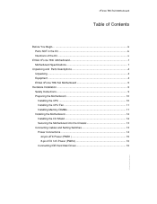
... the Kit ix Intentions of the Kit x EVGA nForce 780i Motherboard 1 Motherboard Specifications 1 Unpacking and Parts Descriptions 4 Unpacking ...4 Equipment ...4 EVGA nForce 780i SLI Motherboard 5 Hardware Installation ...9 Safety Instructions...9 Preparing the Motherboard 10 Installing the CPU 10 Installing the CPU Fan 11 Installing Memory DIMMs 11 Installing the Motherboard 12 Installing the I/O Shield 12 Securing the Motherboard into the Chassis 13 Connecting Cables and...
... the Kit ix Intentions of the Kit x EVGA nForce 780i Motherboard 1 Motherboard Specifications 1 Unpacking and Parts Descriptions 4 Unpacking ...4 Equipment ...4 EVGA nForce 780i SLI Motherboard 5 Hardware Installation ...9 Safety Instructions...9 Preparing the Motherboard 10 Installing the CPU 10 Installing the CPU Fan 11 Installing Memory DIMMs 11 Installing the Motherboard 12 Installing the I/O Shield 12 Securing the Motherboard into the Chassis 13 Connecting Cables and...

User Manual
Page 5
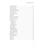
780i 3-Way SLI Motherboard Connecting Serial ATA Cables 18 Connecting Internal Headers 19 Front Panel Header 19 IEEE 1394a ...20 USB Headers 21 Audio ...22 Fan Connections 23 COM1 ...24 FDD Connector 25 Expansion Slots 25 PCI Slots ...25 PCI Express x1 Slot 26 PCI Express x16 Slots 26 Jumper Settings ...27 Clear CMOS Jumper: CLR_CMOS 27 Configuring the BIOS 29 Enter BIOS Setup 30 Main Menu...30 Standard CMOS Features Menu 33 Date and Time...34 IDE Channel and SATA Channel 34 Drive A...37 Halt On ...37 Memory ...38 Advanced BIOS Features 39 Removable Device Priority 40 EVGA iv
780i 3-Way SLI Motherboard Connecting Serial ATA Cables 18 Connecting Internal Headers 19 Front Panel Header 19 IEEE 1394a ...20 USB Headers 21 Audio ...22 Fan Connections 23 COM1 ...24 FDD Connector 25 Expansion Slots 25 PCI Slots ...25 PCI Express x1 Slot 26 PCI Express x16 Slots 26 Jumper Settings ...27 Clear CMOS Jumper: CLR_CMOS 27 Configuring the BIOS 29 Enter BIOS Setup 30 Main Menu...30 Standard CMOS Features Menu 33 Date and Time...34 IDE Channel and SATA Channel 34 Drive A...37 Halt On ...37 Memory ...38 Advanced BIOS Features 39 Removable Device Priority 40 EVGA iv
User Manual
Page 6
nForce 780i SLI Motherboard Hard Disk Boot Priority 40 Network Boot Priority 40 CPU Internal Cache 40 Quick Power On Self Test 41 First/Second/Third Boot Device 41 ...
nForce 780i SLI Motherboard Hard Disk Boot Priority 40 Network Boot Priority 40 CPU Internal Cache 40 Quick Power On Self Test 41 First/Second/Third Boot Device 41 ...
User Manual
Page 7
780i 3-Way SLI Motherboard IEEE1394 controller 62 HD Audio ...62 IDE HDD Block Mode 62 Onboard FDC Controller 62 Onboard Serial Port 1 63 Power Management Setup Menu 63 ACPI ... 70 Installing Drivers and Software 72 Driver Installation 73 Using the NVIDIA Software 74 NVIDIA Performance Group of NVIDIA Control Panel 75 Device Settings 76 EVGA vi
780i 3-Way SLI Motherboard IEEE1394 controller 62 HD Audio ...62 IDE HDD Block Mode 62 Onboard FDC Controller 62 Onboard Serial Port 1 63 Power Management Setup Menu 63 ACPI ... 70 Installing Drivers and Software 72 Driver Installation 73 Using the NVIDIA Software 74 NVIDIA Performance Group of NVIDIA Control Panel 75 Device Settings 76 EVGA vi
User Manual
Page 8
POST Codes for Tritium Platform 94 Appendix B. Configuring an SLI Configuration 104 SLI Connector ...104 ForceWare Driver 105 Enabling 3-Way SLI 107 Verifying 3-way SLI is Active 109 Index...110 nForce 780i SLI Motherboard Current Hardware Settings 77 Dynamic BIOS Access 84 View System Information 85 Profile Policies...86 Manage Your System BIOS 87 NVIDIA System Monitor 88 Appendix A.
POST Codes for Tritium Platform 94 Appendix B. Configuring an SLI Configuration 104 SLI Connector ...104 ForceWare Driver 105 Enabling 3-Way SLI 107 Verifying 3-way SLI is Active 109 Index...110 nForce 780i SLI Motherboard Current Hardware Settings 77 Dynamic BIOS Access 84 View System Information 85 Profile Policies...86 Manage Your System BIOS 87 NVIDIA System Monitor 88 Appendix A.
User Manual
Page 10
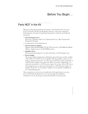
... and the number of the GPUs you are assuming you need a minimum of a 350 W power supply. As a rule, for your new EVGA nForce® 780i SLI motherboard. These instructions tell you how to www.slizone.com. To calculate the power you install. If you have two GPUs in an... GPUs in the Kit This kit contains all the hardware necessary to 1200 MHz SLI-Ready Memory. If you are going to require more power. nForce 780i SLI Motherboard Before You Begin... Parts NOT in an SLI configuration, you are going to SLI two graphics cards, you will need a minimum of a 500 W power supply...
... and the number of the GPUs you are assuming you need a minimum of a 350 W power supply. As a rule, for your new EVGA nForce® 780i SLI motherboard. These instructions tell you how to www.slizone.com. To calculate the power you install. If you have two GPUs in an... GPUs in the Kit This kit contains all the hardware necessary to 1200 MHz SLI-Ready Memory. If you are going to require more power. nForce 780i SLI Motherboard Before You Begin... Parts NOT in an SLI configuration, you are going to SLI two graphics cards, you will need a minimum of a 500 W power supply...

User Manual
Page 11
EVGA x 780i 3-Way SLI Motherboard Intentions of the cables. If however, you are building a PC, you will use most of the cables provided in a PC case, you will need many of the Kit This kit provides you with the motherboard and all connecting cables necessary to reinstall an operating system even though the current drives have an operating system. If you are replacing a motherboard, you will not need to install the motherboard into a PC case. When replacing a motherboard in the kit.
EVGA x 780i 3-Way SLI Motherboard Intentions of the cables. If however, you are building a PC, you will use most of the cables provided in a PC case, you will need many of the Kit This kit provides you with the motherboard and all connecting cables necessary to reinstall an operating system even though the current drives have an operating system. If you are replacing a motherboard, you will not need to install the motherboard into a PC case. When replacing a motherboard in the kit.
User Manual
Page 12
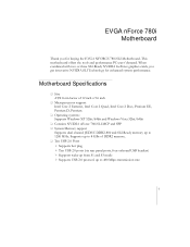
EVGA nForce 780i Motherboard Thank you get innovative NVIDIA SLI Technology for buying the EVGA NFORCE 780i SLI Motherboard. Motherboard Specifications ‰ Size ATX form factor of DDR2 memory. ‰ Ten USB 2.0 Ports ¾ Supports hot plug ¾ Ten USB 2.0 ports (six rear panel ports, ...
EVGA nForce 780i Motherboard Thank you get innovative NVIDIA SLI Technology for buying the EVGA NFORCE 780i SLI Motherboard. Motherboard Specifications ‰ Size ATX form factor of DDR2 memory. ‰ Ten USB 2.0 Ports ¾ Supports hot plug ¾ Ten USB 2.0 ports (six rear panel ports, ...
User Manual
Page 13
780i 3-Way SLI Motherboard EVGA 2 ‰ Onboard Serial ATA II ¾ 300MBps data transfer rate ¾ Six Serial ATA II connectors ¾ NVIDIA MediaShield RAID with support for RAID 0, RAID 1, ...
780i 3-Way SLI Motherboard EVGA 2 ‰ Onboard Serial ATA II ¾ 300MBps data transfer rate ¾ Six Serial ATA II connectors ¾ NVIDIA MediaShield RAID with support for RAID 0, RAID 1, ...

User Manual
Page 14
nForce 780i SLI Motherboard
nForce 780i SLI Motherboard

User Manual
Page 15
... attach a floppy drive to a new chassis. If you may not need many of equipment shipped in the EVGA nForce 780i SLI motherboard box. (Accessories may vary between models, see product package) EVGA nForce 780i SLI Motherboard This PCI Express motherboard contains the NVIDIA nForce 780i SLI SPP and MCP and is missing or damaged, contact your reseller. Be sure to block radio frequency transmissions...
... attach a floppy drive to a new chassis. If you may not need many of equipment shipped in the EVGA nForce 780i SLI motherboard box. (Accessories may vary between models, see product package) EVGA nForce 780i SLI Motherboard This PCI Express motherboard contains the NVIDIA nForce 780i SLI SPP and MCP and is missing or damaged, contact your reseller. Be sure to block radio frequency transmissions...

User Manual
Page 16
... back panels of the chassis. USB 2.0 4-Port Cable Provides four additional USB ports to the motherboard Comm2 Bracket Cable IDE-ATA 133 HDD Cable EVGA nForce 780i SLI Motherboard The EVGA nForce 780i SLI motherboard with the NVIDIA nForce 780i SLI SPP and MCP processors is a PCI Express, SLI-ready motherboard. nForce 780i SLI Motherboard 2-Port SATA Power Cable (Qty Three) 1394 Cable Provides two additional 1394 ports to either...
... back panels of the chassis. USB 2.0 4-Port Cable Provides four additional USB ports to the motherboard Comm2 Bracket Cable IDE-ATA 133 HDD Cable EVGA nForce 780i SLI Motherboard The EVGA nForce 780i SLI motherboard with the NVIDIA nForce 780i SLI SPP and MCP processors is a PCI Express, SLI-ready motherboard. nForce 780i SLI Motherboard 2-Port SATA Power Cable (Qty Three) 1394 Cable Provides two additional 1394 ports to either...

User Manual
Page 17
... 13. Front panel connector 16. Reset Button 19. Azalia HD Audio Header 5 21. PCI Express x1 slot 26. 780i 3-Way SLI Motherboard 22 22 25 23 24 23 23 21 20 19 26 27 28 29 1187 13 1 13 2 16 3 15 4 14 13 11 12 10 9 8 1. SPDIF ... (Figure 2) 27. DDR DIMM Slots 0 - 3 5. 24-pin ATX Power Connector 6. USB headers 12. Heat dissipater 28. 8-pin ATX_12V power connector 29 MCP/SPP fan connector EVGA 6 PCI slots 23. CPU Socket 2. NVIDIA MCP (passive heat sink) 6 7 4 11. FDD connector 9. Fan connector 14. PCI Express x16 slots...
... 13. Front panel connector 16. Reset Button 19. Azalia HD Audio Header 5 21. PCI Express x1 slot 26. 780i 3-Way SLI Motherboard 22 22 25 23 24 23 23 21 20 19 26 27 28 29 1187 13 1 13 2 16 3 15 4 14 13 11 12 10 9 8 1. SPDIF ... (Figure 2) 27. DDR DIMM Slots 0 - 3 5. 24-pin ATX Power Connector 6. USB headers 12. Heat dissipater 28. 8-pin ATX_12V power connector 29 MCP/SPP fan connector EVGA 6 PCI slots 23. CPU Socket 2. NVIDIA MCP (passive heat sink) 6 7 4 11. FDD connector 9. Fan connector 14. PCI Express x16 slots...

User Manual
Page 18
FP Audio connector Figure 1. EVGA nForce 780i SLI Motherboard Layout 7 7 1 2 3 4 5 6 4 4 1. USB 2.0 ports (SIX) 5. Port Blue Green Pink Orange Black Grey 2-Channel Line-In Line-Out Mic In 4-Channel Line-In Front Speaker Out Mic ... = 10 Mbps/Link/Activity • Yellow and Green/Light Up/Blink = 100 Mbps/link/Activity • Green/Light Up/Blink = 1000 Mbps/Link/Activity Figure 2. nForce 780i SLI Motherboard 10.
FP Audio connector Figure 1. EVGA nForce 780i SLI Motherboard Layout 7 7 1 2 3 4 5 6 4 4 1. USB 2.0 ports (SIX) 5. Port Blue Green Pink Orange Black Grey 2-Channel Line-In Line-Out Mic In 4-Channel Line-In Front Speaker Out Mic ... = 10 Mbps/Link/Activity • Yellow and Green/Light Up/Blink = 100 Mbps/link/Activity • Green/Light Up/Blink = 1000 Mbps/Link/Activity Figure 2. nForce 780i SLI Motherboard 10.

User Manual
Page 19
780i 3-Way SLI Motherboard EVGA 8
780i 3-Way SLI Motherboard EVGA 8

User Manual
Page 20
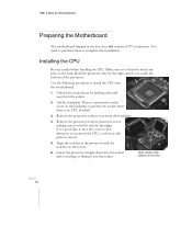
... safety precautions. The topics covered in this section are: ‰ Preparing the motherboard ¾ Installing the CPU ¾ Installing the CPU fan ¾ Installing the memory ‰ Installing the motherboard ‰ Connecting cables and setting switches Safety Instructions To reduce the risk of ...the motherboard. Remember to remove power from your computer by disconnecting the AC main source before removing...
... safety precautions. The topics covered in this section are: ‰ Preparing the motherboard ¾ Installing the CPU ¾ Installing the CPU fan ¾ Installing the memory ‰ Installing the motherboard ‰ Connecting cables and setting switches Safety Instructions To reduce the risk of ...the motherboard. Remember to remove power from your computer by disconnecting the AC main source before removing...
User Manual
Page 21
... CPU EVGA 10 Lift the load plate. It is a good idea to save the cover so that whenever you remove the CPU, you hold it only by the edges. You need to purchase these to install the CPU onto the motherboard. 1. Remove the processor from the load plate. 4. 780i 3-Way SLI Motherboard Preparing the Motherboard The motherboard...
... CPU EVGA 10 Lift the load plate. It is a good idea to save the cover so that whenever you remove the CPU, you hold it only by the edges. You need to purchase these to install the CPU onto the motherboard. 1. Remove the processor from the load plate. 4. 780i 3-Way SLI Motherboard Preparing the Motherboard The motherboard...

User Manual
Page 22
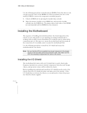
... can install the DIMM into any slot, however, slot 0 is correct for your chassis type and your fan assembly. Be sure that came with this motherboard. They also support dual channel DDR2 memory technology up to ensure normal operation. You can be at least one memory bank populated to 10.7GB... DDR2 memory modules. The idea is fully seated and level in adjacent slots. ‰ Four DIMMS: Install into slots 0, 1, 2, and 3. Installing Memory DIMMs Your new motherboard has four 1.8V 240-pin slots for the location of the memory slots.) ‰ One DIMM: Install into slot 0.
... can install the DIMM into any slot, however, slot 0 is correct for your chassis type and your fan assembly. Be sure that came with this motherboard. They also support dual channel DDR2 memory technology up to ensure normal operation. You can be at least one memory bank populated to 10.7GB... DDR2 memory modules. The idea is fully seated and level in adjacent slots. ‰ Four DIMMS: Install into slots 0, 1, 2, and 3. Installing Memory DIMMs Your new motherboard has four 1.8V 240-pin slots for the location of the memory slots.) ‰ One DIMM: Install into slot 0.
User Manual
Page 23
... chassis you are replacing an existing motherboard or working with an I/O shield that the CPU fan assembly has enough clearance for the chassis covers to lock into place and for the expansion cards. The plastic clips at both sides of the chassis. EVGA 12 780i 3-Way SLI Motherboard Use the following procedure to install... the I/O shield and secure the motherboard into the chassis.
... chassis you are replacing an existing motherboard or working with an I/O shield that the CPU fan assembly has enough clearance for the chassis covers to lock into place and for the expansion cards. The plastic clips at both sides of the chassis. EVGA 12 780i 3-Way SLI Motherboard Use the following procedure to install... the I/O shield and secure the motherboard into the chassis.
