User Manual
Page 2
User Guide EVGA nForce 750i SLI Motherboard
User Guide EVGA nForce 750i SLI Motherboard
User Manual
Page 7
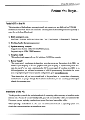
... D, Pentium Cooling fan for your new EVGA nForce® 750i SLI motherboard. If you have two GPUs in an SLI configuration, you will use most of the cables provided in a PC case, you will need many of a 500 W power supply. Intentions of a 350 W power supply. Supports up to make the motherboard functional. nForce 750i SLI Motherboard Before You Begin... As you...
... D, Pentium Cooling fan for your new EVGA nForce® 750i SLI motherboard. If you have two GPUs in an SLI configuration, you will use most of the cables provided in a PC case, you will need many of a 500 W power supply. Intentions of a 350 W power supply. Supports up to make the motherboard functional. nForce 750i SLI Motherboard Before You Begin... As you...
User Manual
Page 8
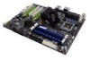
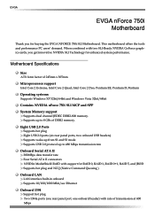
...1394 Support hot plug Two 1394a ports (one rear panel port, one onboard header) with two SLI-Ready NVIDIA GeForce graphics cards, you for buying the EVGA NFORCE 750i SLI Motherboard. Supports up to 8 GBs of DDR2 memory. When combined with rate of 245mm x 305mm...EE, Pentium D, Pentium Operating systems: Supports Windows XP 32bit/64bit and Windows Vista 32bit/64bit Contains NVIDIA nForce 750i SLI MCP and SPP System Memory support Supports dual channel JEDEC DDR2-800 memory. EVGA EVGA nForce 750i Motherboard Thank you get innovative NVIDIA SLI Technology for enhanced system performance.
...1394 Support hot plug Two 1394a ports (one rear panel port, one onboard header) with two SLI-Ready NVIDIA GeForce graphics cards, you for buying the EVGA NFORCE 750i SLI Motherboard. Supports up to 8 GBs of DDR2 memory. When combined with rate of 245mm x 305mm...EE, Pentium D, Pentium Operating systems: Supports Windows XP 32bit/64bit and Windows Vista 32bit/64bit Contains NVIDIA nForce 750i SLI MCP and SPP System Memory support Supports dual channel JEDEC DDR2-800 memory. EVGA EVGA nForce 750i Motherboard Thank you get innovative NVIDIA SLI Technology for enhanced system performance.

User Manual
Page 9
off) Expansion Slots Three PCI slots One PCI Express x1 slot Two PCI Express x16 Graphics slot compliant with PCI Express 2.0 nForce 750i SLI Motherboard Onboard Audio Azalia High-Definition audio Supports 8-channel audio Supports S/PDIF output Supports Jack-Sensing function Green Function Supports ACPI (Advanced Configuration and Power Interface) Supports S0 (normal), S1 (power on suspend), S3 (suspend to RAM), S4 (Suspend to disk depends on OS), and S5 (soft -
off) Expansion Slots Three PCI slots One PCI Express x1 slot Two PCI Express x16 Graphics slot compliant with PCI Express 2.0 nForce 750i SLI Motherboard Onboard Audio Azalia High-Definition audio Supports 8-channel audio Supports S/PDIF output Supports Jack-Sensing function Green Function Supports ACPI (Advanced Configuration and Power Interface) Supports S0 (normal), S1 (power on suspend), S3 (suspend to RAM), S4 (Suspend to disk depends on OS), and S5 (soft -
User Manual
Page 10
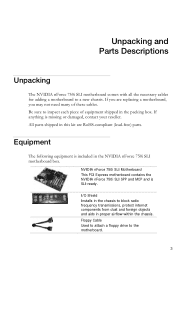
Equipment The following equipment is included in this kit are replacing a motherboard, you are RoHS-compliant (lead-free) parts. NVIDIA nForce 750i SLI Motherboard This PCI Express motherboard contains the NVIDIA nForce 750i SLI SPP and MCP and is missing or damaged, contact your reseller. Floppy Cable Used ... a new chassis. Unpacking and Parts Descriptions Unpacking The NVIDIA nForce 750i SLI motherboard comes with all the necessary cables for adding a motherboard to inspect each piece of these cables. If anything is SLI-ready. If you may not need many of equipment shipped in...
Equipment The following equipment is included in this kit are replacing a motherboard, you are RoHS-compliant (lead-free) parts. NVIDIA nForce 750i SLI Motherboard This PCI Express motherboard contains the NVIDIA nForce 750i SLI SPP and MCP and is missing or damaged, contact your reseller. Floppy Cable Used ... a new chassis. Unpacking and Parts Descriptions Unpacking The NVIDIA nForce 750i SLI motherboard comes with all the necessary cables for adding a motherboard to inspect each piece of these cables. If anything is SLI-ready. If you may not need many of equipment shipped in...

User Manual
Page 11
USB 2.0 4-Port Cable Provides four additional USB ports to either the front or back panels of the chassis. 2-Port SATA Power Cable (Qty Three) 1394 Cable Provides two additional 1394 ports to either the front or back panels of the chassis. SATA Signal Cable (Qty Four) Used to support the Serial ATA protocol and each one connects a single drive to the motherboard Comm2 Bracket Cable IDE-ATA 133 HDD Cable Driver Installation CD SLI Bridge 2-Way
USB 2.0 4-Port Cable Provides four additional USB ports to either the front or back panels of the chassis. 2-Port SATA Power Cable (Qty Three) 1394 Cable Provides two additional 1394 ports to either the front or back panels of the chassis. SATA Signal Cable (Qty Four) Used to support the Serial ATA protocol and each one connects a single drive to the motherboard Comm2 Bracket Cable IDE-ATA 133 HDD Cable Driver Installation CD SLI Bridge 2-Way

User Manual
Page 13
... 26.1394a connector 27. PS/2 Keyboard Port 3. 1394a (Firewire) Port 4. CPU 775 Socket 2. Serial connector 12. Reset button 20. Serial-ATA (SATA) connectors 9. Battery 13. EVGA nForce 750i SLI Backpanel connectors 1. PS/2 Mouse Port 2. nForce 750i SLI Motherboard 1. System fan connector 18. Reset CMOS button 16. SPDIF output 6. PCI slots 25. USB 2.0 ports (Six) 5.
... 26.1394a connector 27. PS/2 Keyboard Port 3. 1394a (Firewire) Port 4. CPU 775 Socket 2. Serial connector 12. Reset button 20. Serial-ATA (SATA) connectors 9. Battery 13. EVGA nForce 750i SLI Backpanel connectors 1. PS/2 Mouse Port 2. nForce 750i SLI Motherboard 1. System fan connector 18. Reset CMOS button 16. SPDIF output 6. PCI slots 25. USB 2.0 ports (Six) 5.

User Manual
Page 15
... while you have a safe place to protect the socket when there is no CPU installed. 3. There is a good idea to install the CPU onto the motherboard. 1. Remove the protective socket cover from the socket. 2. Installing the CPU Fan There are many different fan types that came with the notches on the... to save the cover so that the fan orientation is fully seated and level in the processor with you hold it . 5. Lift the load plate. nForce 750i SLI Motherboard Installing the CPU Be very careful when handling the CPU.
... while you have a safe place to protect the socket when there is no CPU installed. 3. There is a good idea to install the CPU onto the motherboard. 1. Remove the protective socket cover from the socket. 2. Installing the CPU Fan There are many different fan types that came with the notches on the... to save the cover so that the fan orientation is fully seated and level in the processor with you hold it . 5. Lift the load plate. nForce 750i SLI Motherboard Installing the CPU Be very careful when handling the CPU.

User Manual
Page 17
...or spacers to allow the mother board to be easier to make all the connections prior to this step or to secure the motherboard first. If the I /O shield that is recommended that you would be secured to the chassis and help to block radio ... install the I /O shield. 4. Secure the motherboard with the vents on the covers. If there are replacing an existing motherboard or working with an empty chassis. Determine if it fits securely. nForce 750i SLI Motherboard Installing the Motherboard The sequence of installing the motherboard into the chassis depends on the chassis you are...
...or spacers to allow the mother board to be easier to make all the connections prior to this step or to secure the motherboard first. If the I /O shield that is recommended that you would be secured to the chassis and help to block radio ... install the I /O shield. 4. Secure the motherboard with the vents on the covers. If there are replacing an existing motherboard or working with an empty chassis. Determine if it fits securely. nForce 750i SLI Motherboard Installing the Motherboard The sequence of installing the motherboard into the chassis depends on the chassis you are...

User Manual
Page 19
Make sure that the power supply cable and pins are properly aligned with the connector on the motherboard. v Pin Assignments Connector Pin Signal 1 GND 2 GND 3 GND 4 GND Pin Signal 5 +12V 6 +12V 7 +12V 8 +12V 11 Align the pins to the DIMM slots. v Pin Assignments ... power connection, is secure. Firmly plug the power supply cable into the connector and make sure it is used to provide power to the CPU. nForce 750i SLI Motherboard Power Connections 24-pin ATX Power PWR1 is the main power supply connector located along the edge of the board next to the connector and...
Make sure that the power supply cable and pins are properly aligned with the connector on the motherboard. v Pin Assignments Connector Pin Signal 1 GND 2 GND 3 GND 4 GND Pin Signal 5 +12V 6 +12V 7 +12V 8 +12V 11 Align the pins to the DIMM slots. v Pin Assignments ... power connection, is secure. Firmly plug the power supply cable into the connector and make sure it is used to provide power to the CPU. nForce 750i SLI Motherboard Power Connections 24-pin ATX Power PWR1 is the main power supply connector located along the edge of the board next to the connector and...

User Manual
Page 21
...thin Serial ATA II cables for primary storage devices. The current Serial ATA II interface allows up to the motherboard. There are four serial ATA connectors on the motherboard that support RAID 0,RAID 1, RAID 5, RAID 0+1 and JBOD configurations. v Pin Assignments Connector SATA B1... SATA B0 SATA A0 (bottom) SATA A1 (top) Pin Signal 1 GND 2 TX+ 3 TX- 4 GND 5 RX+ 6 RX- 7 GND Connecting Floppy Disk Drive The motherboard supports a standard 360K, 720K, 1.2M, 1.44m, and a 2.88M floppy disk drive (FDD). nForce 750i SLI Motherboard Connecting Serial ATA Cables The Serial ATA II...
...thin Serial ATA II cables for primary storage devices. The current Serial ATA II interface allows up to the motherboard. There are four serial ATA connectors on the motherboard that support RAID 0,RAID 1, RAID 5, RAID 0+1 and JBOD configurations. v Pin Assignments Connector SATA B1... SATA B0 SATA A0 (bottom) SATA A1 (top) Pin Signal 1 GND 2 TX+ 3 TX- 4 GND 5 RX+ 6 RX- 7 GND Connecting Floppy Disk Drive The motherboard supports a standard 360K, 720K, 1.2M, 1.44m, and a 2.88M floppy disk drive (FDD). nForce 750i SLI Motherboard Connecting Serial ATA Cables The Serial ATA II...
User Manual
Page 23
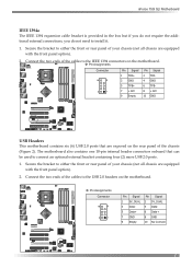
nForce 750i SLI Motherboard IEEE 1394a The IEEE 1394 expansion cable bracket is provided in ... external bracket containing four (2) more USB 2.0 ports. 1. Connect the two ends of the cables to the USB 2.0 headers on the motherboard. v Pin Assignments Connector Pin Signal 1 5V_DUAL 3 Data5 Data+ 7 GND 9 Empty Pin Signal 2 5V_DUAL 4 Data6 Data+ 8... GND 10 No Connect Connect the two ends of the cables to the IEEE 1394 connectors on the motherboard. Secure the bracket to either the front or rear panel of the chassis (Figure 2). Secure the bracket to either the...
nForce 750i SLI Motherboard IEEE 1394a The IEEE 1394 expansion cable bracket is provided in ... external bracket containing four (2) more USB 2.0 ports. 1. Connect the two ends of the cables to the USB 2.0 headers on the motherboard. v Pin Assignments Connector Pin Signal 1 5V_DUAL 3 Data5 Data+ 7 GND 9 Empty Pin Signal 2 5V_DUAL 4 Data6 Data+ 8... GND 10 No Connect Connect the two ends of the cables to the IEEE 1394 connectors on the motherboard. Secure the bracket to either the front or rear panel of the chassis (Figure 2). Secure the bracket to either the...

User Manual
Page 25
... Others FAN: There are four more fan connectors on the motherboard. v Pin Assignments Connector Pin Signal 1 CONTROL 2 SENSE 3 +12V 4 GND Connector Pin Signal 1 SENSE 2 +12V 3 +12V CHASSIS FAN2 NFORCE FAN: Install the fan over the nForce 750i SLI SPP to this installation, these may not be either a ... the system enters S3, S4 and S5 mode. CPU FAN NFORCE FAN CPU FAN: Connect the CPU fan to draw heat from the MCP. nForce 750i SLI Motherboard Fan Connections There are six fan connections on the motherboard. For this connrctor. The fan speed can be used. Connect...
... Others FAN: There are four more fan connectors on the motherboard. v Pin Assignments Connector Pin Signal 1 CONTROL 2 SENSE 3 +12V 4 GND Connector Pin Signal 1 SENSE 2 +12V 3 +12V CHASSIS FAN2 NFORCE FAN: Install the fan over the nForce 750i SLI SPP to this installation, these may not be either a ... the system enters S3, S4 and S5 mode. CPU FAN NFORCE FAN CPU FAN: Connect the CPU fan to draw heat from the MCP. nForce 750i SLI Motherboard Fan Connections There are six fan connections on the motherboard. For this connrctor. The fan speed can be used. Connect...

User Manual
Page 26
EVGA Expansion Slots The EVGA nForce 750i SLI motherboard contains six expansion slots, three PCI Express slots and three PCI slots. When installing a card into the PCI slot, be sure that is fully seated. The x1 slot provides 250 MB/sec bandwidth. The design of PCI Express x16 graphics card supported by this motherboard ... one PCI Express x1 slot that it could cause a short across the pins. For a full list of this motherboard, go to hold the blank cover. For SLI Mode, an SLI kit must be sure the retention clip snaps and locks the card into the "PCIE X16_1" VGA slot. (labeled...
EVGA Expansion Slots The EVGA nForce 750i SLI motherboard contains six expansion slots, three PCI Express slots and three PCI slots. When installing a card into the PCI slot, be sure that is fully seated. The x1 slot provides 250 MB/sec bandwidth. The design of PCI Express x16 graphics card supported by this motherboard ... one PCI Express x1 slot that it could cause a short across the pins. For a full list of this motherboard, go to hold the blank cover. For SLI Mode, an SLI kit must be sure the retention clip snaps and locks the card into the "PCIE X16_1" VGA slot. (labeled...

User Manual
Page 27
Allows quick and easy optimization. CMOS Button: The motherboard uses the CMOS RAM to boot. nForce 750i SLI Motherboard Onboard Buttons These onboard buttons include RESET, POWER and CMOS , lets you turn on/off the system easily, and convenient for clear CMOS RESET and ...
Allows quick and easy optimization. CMOS Button: The motherboard uses the CMOS RAM to boot. nForce 750i SLI Motherboard Onboard Buttons These onboard buttons include RESET, POWER and CMOS , lets you turn on/off the system easily, and convenient for clear CMOS RESET and ...

User Manual
Page 28
... maintain optimal system performance. Note: It is critical to enter Setup. Use the following procedure to change the system settings through the BIOS Setup menus. nForce 750i SLI Motherboard Configuring the BIOS This section discusses how to verify/change BIOS settings. 1. Detailed descriptions of the screen during the Power On Self Test (POST). Power...
... maintain optimal system performance. Note: It is critical to enter Setup. Use the following procedure to change the system settings through the BIOS Setup menus. nForce 750i SLI Motherboard Configuring the BIOS This section discusses how to verify/change BIOS settings. 1. Detailed descriptions of the screen during the Power On Self Test (POST). Power...
User Manual
Page 30
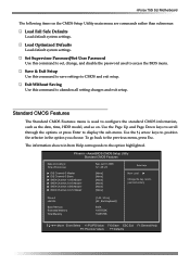
nForce 750i SLI Motherboard The following items on . Exit Without Saving Use this command to save settings to access the BIOS menu. Standard CMOS Features The Standard CMOS Features ... Setup Utility Standard CMOS Features Date (mm:dd:yy) Time (hh:mm:ss) IDE Channel 0 Master IDE Channel 0 Slave SATA Channel 1 (A0) Master SATA Channel 2 (A1) Master SATA Channel 3 (B0) Master SATA Channel 4 (C1) Master Sat, Jul 01 2006 12 : 48: 23 [None] [None] [None] [None] [None] [None] Item Help Main...
nForce 750i SLI Motherboard The following items on . Exit Without Saving Use this command to save settings to access the BIOS menu. Standard CMOS Features The Standard CMOS Features ... Setup Utility Standard CMOS Features Date (mm:dd:yy) Time (hh:mm:ss) IDE Channel 0 Master IDE Channel 0 Slave SATA Channel 1 (A0) Master SATA Channel 2 (A1) Master SATA Channel 3 (B0) Master SATA Channel 4 (C1) Master Sat, Jul 01 2006 12 : 48: 23 [None] [None] [None] [None] [None] [None] Item Help Main...

User Manual
Page 32
..., the system boots from some other device if the first/second/third boot devices fail. Boot Up NumLock Status This option allows you enter setup. nForce 750i SLI Motherboard the + or - To go back to see the list of NumLock.
..., the system boots from some other device if the first/second/third boot devices fail. Boot Up NumLock Status This option allows you enter setup. nForce 750i SLI Motherboard the + or - To go back to see the list of NumLock.

User Manual
Page 34
nForce 750i SLI Motherboard Integrated Peripherals Menu Select Integrated Peripherals from Auto, or Mode 1 through Mode 4. Phoenix - Primary Master/Slave UDMA When OnChip IDE Channel0 is set to [Enabled], ...
nForce 750i SLI Motherboard Integrated Peripherals Menu Select Integrated Peripherals from Auto, or Mode 1 through Mode 4. Phoenix - Primary Master/Slave UDMA When OnChip IDE Channel0 is set to [Enabled], ...
User Manual
Page 36
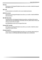
...] to Auto or disable their functions. Onboard Serial Port 1 This function on the Integrated Peripherals menu allows you to select the onboard serial port 1 function. nForce 750i SLI Motherboard HD Audio This function on the Integrated Peripherals menu allows your drive does not support block mode. MAC LAN Use these functions to set the...
...] to Auto or disable their functions. Onboard Serial Port 1 This function on the Integrated Peripherals menu allows you to select the onboard serial port 1 function. nForce 750i SLI Motherboard HD Audio This function on the Integrated Peripherals menu allows your drive does not support block mode. MAC LAN Use these functions to set the...
