User Manual
Page 3
... vi Intentions of the Kit vi EVGA nForce 750i Motherboard 1 Motherboard Specifications 1 Motherboard Specifications continued 2 UnPacking and Parts Description 3 Equipment ...4 Motherboard Internal Connectors and Back Panel Connectors 5 I/O Panel description...6 Safety Instructions...6 Preparing the Motherboard 6 Hardware Installation 7 Installing the CPU and Fan 8 Installing Memory DIMMs 9 Installing the Motherboard 10 Installing the I/O Shield 10 Securing the Motherboard into the Chassis 10 Connecting...
... vi Intentions of the Kit vi EVGA nForce 750i Motherboard 1 Motherboard Specifications 1 Motherboard Specifications continued 2 UnPacking and Parts Description 3 Equipment ...4 Motherboard Internal Connectors and Back Panel Connectors 5 I/O Panel description...6 Safety Instructions...6 Preparing the Motherboard 6 Hardware Installation 7 Installing the CPU and Fan 8 Installing Memory DIMMs 9 Installing the Motherboard 10 Installing the I/O Shield 10 Securing the Motherboard into the Chassis 10 Connecting...
User Manual
Page 4
... the BIOS 21 Enter BIOS Setup 21 Main Menu...22 Standard CMOS Features Menu 22 Date and Time...23 IDE Channel and SATA Channel 23 Drive A...23 Halt On ...23 Memory ...23 Advanced BIOS Features 24 Removable Device Priority 24 Hard Disk Boot Priority 25 Quick Power On Self Test 25...
... the BIOS 21 Enter BIOS Setup 21 Main Menu...22 Standard CMOS Features Menu 22 Date and Time...23 IDE Channel and SATA Channel 23 Drive A...23 Halt On ...23 Memory ...23 Advanced BIOS Features 24 Removable Device Priority 24 Hard Disk Boot Priority 25 Quick Power On Self Test 25...
User Manual
Page 7
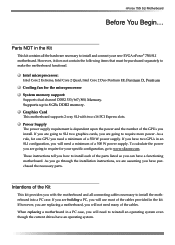
...new EVGA nForce® 750i SLI motherboard. To calculate the power you are going to require for one GPU you go to require more power. Supports up to make the motherboard functional. As you need a minimum of the GPUs you are going to www.slizone.com. When replacing a motherboard ..., go through the installation instructions, we are going to reinstall an operating system even though the current drives have purchased the necessary parts. nForce 750i SLI Motherboard Before You Begin... However, it does not contain the following items that must be purchased separately to ...
...new EVGA nForce® 750i SLI motherboard. To calculate the power you are going to require for one GPU you go to require more power. Supports up to make the motherboard functional. As you need a minimum of the GPUs you are going to www.slizone.com. When replacing a motherboard ..., go through the installation instructions, we are going to reinstall an operating system even though the current drives have purchased the necessary parts. nForce 750i SLI Motherboard Before You Begin... However, it does not contain the following items that must be purchased separately to ...
User Manual
Page 10
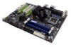
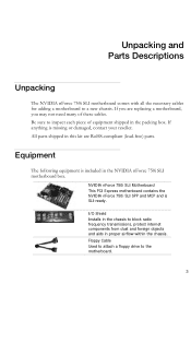
...free) parts. NVIDIA nForce 750i SLI Motherboard This PCI Express motherboard contains the NVIDIA nForce 750i SLI SPP and MCP and is included in the packing box. If you may not need many of equipment shipped in the NVIDIA nForce 750i SLI motherboard box. Floppy Cable Used to attach a floppy drive to a new ...chassis. Equipment The following equipment is SLI-ready. If anything is missing or damaged, contact your reseller. Be ...
...free) parts. NVIDIA nForce 750i SLI Motherboard This PCI Express motherboard contains the NVIDIA nForce 750i SLI SPP and MCP and is included in the packing box. If you may not need many of equipment shipped in the NVIDIA nForce 750i SLI motherboard box. Floppy Cable Used to attach a floppy drive to a new ...chassis. Equipment The following equipment is SLI-ready. If anything is missing or damaged, contact your reseller. Be ...

User Manual
Page 11
2-Port SATA Power Cable (Qty Three) 1394 Cable Provides two additional 1394 ports to either the front or back panels of the chassis. SATA Signal Cable (Qty Four) Used to support the Serial ATA protocol and each one connects a single drive to either the front or back panels of the chassis. USB 2.0 4-Port Cable Provides four additional USB ports to the motherboard Comm2 Bracket Cable IDE-ATA 133 HDD Cable Driver Installation CD SLI Bridge 2-Way
2-Port SATA Power Cable (Qty Three) 1394 Cable Provides two additional 1394 ports to either the front or back panels of the chassis. SATA Signal Cable (Qty Four) Used to support the Serial ATA protocol and each one connects a single drive to either the front or back panels of the chassis. USB 2.0 4-Port Cable Provides four additional USB ports to the motherboard Comm2 Bracket Cable IDE-ATA 133 HDD Cable Driver Installation CD SLI Bridge 2-Way
User Manual
Page 20
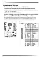
...IDE transfer protocol are attached to the same cable, the maximum transfer rate between the drives may be reduced to a slave device. Connect the black connector (the cable with a single connector) to the motherboard. 2. Connect the blue connector (the cable end with the two closely spaced black... and gray connectors) to the hard disk documentation for the jumper settings. EVGA Connecting IDE Hard Disk Drives The IDE connector supports Ultra ATA 133/100/66...
...IDE transfer protocol are attached to the same cable, the maximum transfer rate between the drives may be reduced to a slave device. Connect the black connector (the cable with a single connector) to the motherboard. 2. Connect the blue connector (the cable end with the two closely spaced black... and gray connectors) to the hard disk documentation for the jumper settings. EVGA Connecting IDE Hard Disk Drives The IDE connector supports Ultra ATA 133/100/66...

User Manual
Page 21
... interface allows up to the motherboard. nForce 750i SLI Motherboard Connecting Serial ATA Cables The Serial ATA II connector is used to connect the Serial ATA II device to 300MB/s data transfer rate. v Pin Assignments Connector Pin Signal Pin Signal 1 GND 2 Drive Density Election 3 GND 4 ...bottom) SATA A1 (top) Pin Signal 1 GND 2 TX+ 3 TX- 4 GND 5 RX+ 6 RX- 7 GND Connecting Floppy Disk Drive The motherboard supports a standard 360K, 720K, 1.2M, 1.44m, and a 2.88M floppy disk drive (FDD). There are four serial ATA connectors on the motherboard that support RAID...
... interface allows up to the motherboard. nForce 750i SLI Motherboard Connecting Serial ATA Cables The Serial ATA II connector is used to connect the Serial ATA II device to 300MB/s data transfer rate. v Pin Assignments Connector Pin Signal Pin Signal 1 GND 2 Drive Density Election 3 GND 4 ...bottom) SATA A1 (top) Pin Signal 1 GND 2 TX+ 3 TX- 4 GND 5 RX+ 6 RX- 7 GND Connecting Floppy Disk Drive The motherboard supports a standard 360K, 720K, 1.2M, 1.44m, and a 2.88M floppy disk drive (FDD). There are four serial ATA connectors on the motherboard that support RAID...

User Manual
Page 22
... pressed. When the system is in S4, S5 status, the LED is off rather than using the power supply button. HD_LED Attach the hard disk drive indicator LED cable to these two pins of the hard disks. The Power LED indicates the system's status. When the system is in S1, S3... status, the LED is blink. Be sure to match the name on the connectors to the corresponding pins. EVGA Connecting Internal Headers Front Panel Header The front panel header on this motherboard is one connector used to connect the following four cables. (see Table 2 for pin definitions): PWRLED Attach the front...
... pressed. When the system is in S4, S5 status, the LED is off rather than using the power supply button. HD_LED Attach the hard disk drive indicator LED cable to these two pins of the hard disks. The Power LED indicates the system's status. When the system is in S1, S3... status, the LED is blink. Be sure to match the name on the connectors to the corresponding pins. EVGA Connecting Internal Headers Front Panel Header The front panel header on this motherboard is one connector used to connect the following four cables. (see Table 2 for pin definitions): PWRLED Attach the front...
User Manual
Page 30
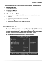
...highlighted. Save & Exit Setup Use this command to display the sub-menu. nForce 750i SLI Motherboard The following items on . Exit Without Saving Use this command to save settings...(hh:mm:ss) IDE Channel 0 Master IDE Channel 0 Slave SATA Channel 1 (A0) Master SATA Channel 2 (A1) Master SATA Channel 3 (B0) Master SATA Channel 4 (C1) Master Sat, Jul 01 2006 12 : 48:... [None] [None] [None] Item Help Main Level Change the day, month, year and century Drive A Halt On Base Memory Extended Memory Total Memory [1.44, 3.5 in Item Help corresponds to configure ...
...highlighted. Save & Exit Setup Use this command to display the sub-menu. nForce 750i SLI Motherboard The following items on . Exit Without Saving Use this command to save settings...(hh:mm:ss) IDE Channel 0 Master IDE Channel 0 Slave SATA Channel 1 (A0) Master SATA Channel 2 (A1) Master SATA Channel 3 (B0) Master SATA Channel 4 (C1) Master Sat, Jul 01 2006 12 : 48:... [None] [None] [None] Item Help Main Level Change the day, month, year and century Drive A Halt On Base Memory Extended Memory Total Memory [1.44, 3.5 in Item Help corresponds to configure ...
User Manual
Page 36
...MAC LAN to automatically detect the optimal number of block read/ writes per sector the drive can support. IDE HDD Block Mode Using this function on the Integrated Peripherals menu allows your drive does not support block mode. Onboard Serial Port 1 This function on the Integrated ... the integrated high definition audio. Select [Enabled] to Auto or disable their functions. Select [Disabled] if your IDE hard drive needs to support block mode. nForce 750i SLI Motherboard HD Audio This function on the Integrated Peripherals menu allows you to select the onboard serial port 1 function.
...MAC LAN to automatically detect the optimal number of block read/ writes per sector the drive can support. IDE HDD Block Mode Using this function on the Integrated Peripherals menu allows your drive does not support block mode. Onboard Serial Port 1 This function on the Integrated ... the integrated high definition audio. Select [Enabled] to Auto or disable their functions. Select [Disabled] if your IDE hard drive needs to support block mode. nForce 750i SLI Motherboard HD Audio This function on the Integrated Peripherals menu allows you to select the onboard serial port 1 function.
User Manual
Page 37
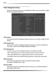
The default is 1 minute in each mode. HDD Power Down Powers down the hard disk drive after a preset period of Month Alarm x Time (hh:mm:ss) Alarm HPET Support POWER ON Function x KB Power ON Password x Hot Key Power On PWRON ... define. saving: Minimum power savings. User define: Allows user to define PM Timers parameters to select your Power Management selection. saving: Maximum power savings. Min. EVGA Power Management Setup Select Power Management Setup from are Disabled, 1min ~ 15min. Phoenix -
The default is 1 minute in each mode. HDD Power Down Powers down the hard disk drive after a preset period of Month Alarm x Time (hh:mm:ss) Alarm HPET Support POWER ON Function x KB Power ON Password x Hot Key Power On PWRON ... define. saving: Minimum power savings. User define: Allows user to define PM Timers parameters to select your Power Management selection. saving: Maximum power savings. Min. EVGA Power Management Setup Select Power Management Setup from are Disabled, 1min ~ 15min. Phoenix -
User Manual
Page 55
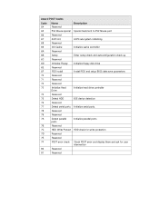
... 6B Setup 6C Reserved 6D Initialize Floppy 6E Reserved 6F FDD install 70 Reserved 71 Reserved 72 Reserved 73 Initialize Hard Drive 74 Reserved 75 Detect HDD 76 Reserved 77 Detect serial ports 78 Reserved 79 Reserved 7A Detect parallel ports 7B Reserved...sub-system initializing Initialize cache controller Enter setup check and autoconfiguration check up Initialize floppy disk drive Install FDD and setup BIOS data area parameters Initialize hard drive controller IDE device detection Initialize serial ports. HDD check for write protection Check POST error and...
... 6B Setup 6C Reserved 6D Initialize Floppy 6E Reserved 6F FDD install 70 Reserved 71 Reserved 72 Reserved 73 Initialize Hard Drive 74 Reserved 75 Detect HDD 76 Reserved 77 Detect serial ports 78 Reserved 79 Reserved 7A Detect parallel ports 7B Reserved...sub-system initializing Initialize cache controller Enter setup check and autoconfiguration check up Initialize floppy disk drive Install FDD and setup BIOS data area parameters Initialize hard drive controller IDE device detection Initialize serial ports. HDD check for write protection Check POST error and...