User Manual
Page 2
User Guide EVGA nForce 750i SLI Motherboard
User Guide EVGA nForce 750i SLI Motherboard
User Manual
Page 3
... vi Intentions of the Kit vi EVGA nForce 750i Motherboard 1 Motherboard Specifications 1 Motherboard Specifications continued 2 UnPacking and Parts Description 3 Equipment ...4 Motherboard Internal Connectors and Back Panel Connectors 5 I/O Panel description...6 Safety Instructions...6 Preparing the Motherboard 6 Hardware Installation 7 Installing the CPU and Fan 8 Installing Memory DIMMs 9 Installing the Motherboard 10 Installing the I/O Shield 10 Securing the Motherboard into the Chassis 10 Connecting...
... vi Intentions of the Kit vi EVGA nForce 750i Motherboard 1 Motherboard Specifications 1 Motherboard Specifications continued 2 UnPacking and Parts Description 3 Equipment ...4 Motherboard Internal Connectors and Back Panel Connectors 5 I/O Panel description...6 Safety Instructions...6 Preparing the Motherboard 6 Hardware Installation 7 Installing the CPU and Fan 8 Installing Memory DIMMs 9 Installing the Motherboard 10 Installing the I/O Shield 10 Securing the Motherboard into the Chassis 10 Connecting...
User Manual
Page 4
IEEE 1394a ...16 USB Headers 16 Audio ...17 COM 1 ...17 Fan Connections 18 Expansion Slots 19 PCI Slots ...19 PCI Express x1 Slot 19 PCI Express x16 Slots 19 Onboard Buttons ...20 Configuring the BIOS 21 Enter BIOS Setup 21 Main Menu...22 Standard CMOS Features Menu 22 Date and Time...23 IDE Channel and SATA Channel 23 Drive A...23 Halt On ...23 Memory ...23 Advanced BIOS Features 24 Removable Device Priority 24 Hard Disk Boot Priority 25 Quick Power On Self Test 25 First/Second/Third Boot Device 25 Boot Other Device 25 Boot Up NumLock Status 25 Security Option 25 APIC Mode ...
IEEE 1394a ...16 USB Headers 16 Audio ...17 COM 1 ...17 Fan Connections 18 Expansion Slots 19 PCI Slots ...19 PCI Express x1 Slot 19 PCI Express x16 Slots 19 Onboard Buttons ...20 Configuring the BIOS 21 Enter BIOS Setup 21 Main Menu...22 Standard CMOS Features Menu 22 Date and Time...23 IDE Channel and SATA Channel 23 Drive A...23 Halt On ...23 Memory ...23 Advanced BIOS Features 24 Removable Device Priority 24 Hard Disk Boot Priority 25 Quick Power On Self Test 25 First/Second/Third Boot Device 25 Boot Other Device 25 Boot Up NumLock Status 25 Security Option 25 APIC Mode ...
User Manual
Page 5
Advanced Chipset Features 26 Spread Spectrum 26 System BIOS Cacheable 26 Integrated Peripherals Menu 27 IDE Function Setup 27 RAID Config ...28 USB Config...28 MAC Config ...28 HD Audio ...29 IEEE1394 controller 29 IDE HDD Block Mode 29 Onboard FDC Controller 29 Onboard Serial Port 1 29 Power Management Setup Menu 30 ACPI Function ...30 ACPI Suspend Type 30 Power Management 30 HDD Power Down 30 Soft-Off by PBNT 30 WOL(PME#) From Soft-Off 31 Power On by Alarm 31 HPET Function 31 POWER ON Function 31 PWRON After PWR-Fail 32
Advanced Chipset Features 26 Spread Spectrum 26 System BIOS Cacheable 26 Integrated Peripherals Menu 27 IDE Function Setup 27 RAID Config ...28 USB Config...28 MAC Config ...28 HD Audio ...29 IEEE1394 controller 29 IDE HDD Block Mode 29 Onboard FDC Controller 29 Onboard Serial Port 1 29 Power Management Setup Menu 30 ACPI Function ...30 ACPI Suspend Type 30 Power Management 30 HDD Power Down 30 Soft-Off by PBNT 30 WOL(PME#) From Soft-Off 31 Power On by Alarm 31 HPET Function 31 POWER ON Function 31 PWRON After PWR-Fail 32
User Manual
Page 6
PnP/PCI Configuration Menu 32 Init Display First 32 Reset Configuration Data 32 Resources Controlled By 33 IRQ Resources 33 PCI/VGA Palette Snoop 33 Maximum Payload Size 33 PC Health Status 34 Dynamic Fan Control 34 Frequency/Voltage Control 35 CPU Clock Ratio 35 LDT Frequency 35 System Clocks 35 FSB & Memory Config 36 FSB Memory Clock Mode 36 Memory Timing Settings 37 System Voltages 38 CPU Core ...38 CPU FSB...38 System Monitor Menu Installing Drivers and Software Driver Installation Appendix A. POST Codes
PnP/PCI Configuration Menu 32 Init Display First 32 Reset Configuration Data 32 Resources Controlled By 33 IRQ Resources 33 PCI/VGA Palette Snoop 33 Maximum Payload Size 33 PC Health Status 34 Dynamic Fan Control 34 Frequency/Voltage Control 35 CPU Clock Ratio 35 LDT Frequency 35 System Clocks 35 FSB & Memory Config 36 FSB Memory Clock Mode 36 Memory Timing Settings 37 System Voltages 38 CPU Core ...38 CPU FSB...38 System Monitor Menu Installing Drivers and Software Driver Installation Appendix A. POST Codes
User Manual
Page 7
... kit provides you install. Intel microprocessor: Intel Core 2 Extreme, Intel Core 2 Quad, Intel Core 2 Duo Pentium EE, Pentium D, Pentium Cooling fan for your new EVGA nForce® 750i SLI motherboard. Power Supply The power supply requirement is dependent upon the power and the number of a 500 W power supply. If however, you are going to reinstall...
... kit provides you install. Intel microprocessor: Intel Core 2 Extreme, Intel Core 2 Quad, Intel Core 2 Duo Pentium EE, Pentium D, Pentium Cooling fan for your new EVGA nForce® 750i SLI motherboard. Power Supply The power supply requirement is dependent upon the power and the number of a 500 W power supply. If however, you are going to reinstall...
User Manual
Page 8
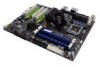
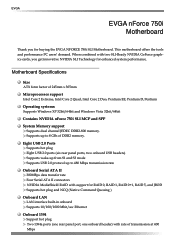
EVGA EVGA nForce 750i Motherboard Thank you get innovative NVIDIA SLI Technology for buying the EVGA NFORCE 750i SLI Motherboard. This motherboard offers the tools and performance PC users' demand. Eight USB 2.0 Ports Supports hot plug Eight USB 2.0 ports (six rear ... at 400 Mbps Motherboard Specifications Size ATX form factor of 245mm x 305mm Microprocessor support Intel Core 2 Extreme, Intel Core 2 Quad, Intel Core 2 Duo, Pentium EE, Pentium D, Pentium Operating systems: Supports Windows XP 32bit/64bit and Windows Vista 32bit/64bit Contains NVIDIA nForce 750i SLI MCP and SPP ...
EVGA EVGA nForce 750i Motherboard Thank you get innovative NVIDIA SLI Technology for buying the EVGA NFORCE 750i SLI Motherboard. This motherboard offers the tools and performance PC users' demand. Eight USB 2.0 Ports Supports hot plug Eight USB 2.0 ports (six rear ... at 400 Mbps Motherboard Specifications Size ATX form factor of 245mm x 305mm Microprocessor support Intel Core 2 Extreme, Intel Core 2 Quad, Intel Core 2 Duo, Pentium EE, Pentium D, Pentium Operating systems: Supports Windows XP 32bit/64bit and Windows Vista 32bit/64bit Contains NVIDIA nForce 750i SLI MCP and SPP ...

User Manual
Page 9
nForce 750i SLI Motherboard Onboard Audio Azalia High-Definition audio Supports 8-channel audio Supports S/PDIF output Supports Jack-Sensing function Green Function Supports ACPI (Advanced Configuration and Power Interface) Supports S0 (normal), S1 (power on suspend), S3 (suspend to RAM), S4 (Suspend to disk depends on OS), and S5 (soft - off) Expansion Slots Three PCI slots One PCI Express x1 slot Two PCI Express x16 Graphics slot compliant with PCI Express 2.0
nForce 750i SLI Motherboard Onboard Audio Azalia High-Definition audio Supports 8-channel audio Supports S/PDIF output Supports Jack-Sensing function Green Function Supports ACPI (Advanced Configuration and Power Interface) Supports S0 (normal), S1 (power on suspend), S3 (suspend to RAM), S4 (Suspend to disk depends on OS), and S5 (soft - off) Expansion Slots Three PCI slots One PCI Express x1 slot Two PCI Express x16 Graphics slot compliant with PCI Express 2.0
User Manual
Page 10
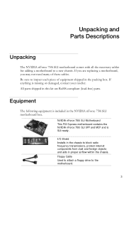
... The following equipment is missing or damaged, contact your reseller. NVIDIA nForce 750i SLI Motherboard This PCI Express motherboard contains the NVIDIA nForce 750i SLI SPP and MCP and is SLI-ready. Unpacking and Parts Descriptions Unpacking The NVIDIA nForce 750i SLI motherboard comes with all the necessary cables for adding a motherboard to block radio frequency transmissions, protect internet components from dust and foreign...
... The following equipment is missing or damaged, contact your reseller. NVIDIA nForce 750i SLI Motherboard This PCI Express motherboard contains the NVIDIA nForce 750i SLI SPP and MCP and is SLI-ready. Unpacking and Parts Descriptions Unpacking The NVIDIA nForce 750i SLI motherboard comes with all the necessary cables for adding a motherboard to block radio frequency transmissions, protect internet components from dust and foreign...

User Manual
Page 11
2-Port SATA Power Cable (Qty Three) 1394 Cable Provides two additional 1394 ports to either the front or back panels of the chassis. SATA Signal Cable (Qty Four) Used to support the Serial ATA protocol and each one connects a single drive to either the front or back panels of the chassis. USB 2.0 4-Port Cable Provides four additional USB ports to the motherboard Comm2 Bracket Cable IDE-ATA 133 HDD Cable Driver Installation CD SLI Bridge 2-Way
2-Port SATA Power Cable (Qty Three) 1394 Cable Provides two additional 1394 ports to either the front or back panels of the chassis. SATA Signal Cable (Qty Four) Used to support the Serial ATA protocol and each one connects a single drive to either the front or back panels of the chassis. USB 2.0 4-Port Cable Provides four additional USB ports to the motherboard Comm2 Bracket Cable IDE-ATA 133 HDD Cable Driver Installation CD SLI Bridge 2-Way

User Manual
Page 13
.... Azalia HD Audio Header 22. Backpanel connectors (Figure 2) 29. 8-pin ATX_12V power connector 30. Chipset fan connector 1 7 2 3 4 5 6 4 4 Figure 2. nForce 750i SLI Motherboard 1. CPU fan connector 3. Post port 10. Auxiliary fan connector 17. SPDIF connector 24. EVGA nForce 750i SLI Backpanel connectors 1. SPDIF output 6. Front panel connector 14. Reset button 20. PS/2 Keyboard Port 3. 1394a (Firewire) Port 4. Audio Port...
.... Azalia HD Audio Header 22. Backpanel connectors (Figure 2) 29. 8-pin ATX_12V power connector 30. Chipset fan connector 1 7 2 3 4 5 6 4 4 Figure 2. nForce 750i SLI Motherboard 1. CPU fan connector 3. Post port 10. Auxiliary fan connector 17. SPDIF connector 24. EVGA nForce 750i SLI Backpanel connectors 1. SPDIF output 6. Front panel connector 14. Reset button 20. PS/2 Keyboard Port 3. 1394a (Firewire) Port 4. Audio Port...
User Manual
Page 14
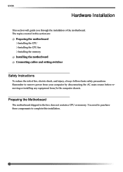
The topics covered in the box does not contain a CPU or memory. Preparing the Motherboard The motherboard shipped in this installation. 7 You need to purchase these components to the computer chassis. Remember to remove power from your...any equipment from/to complete this section are: Preparing the motherboard Installing the CPU Installing the CPU fan Installing the memory Installing the motherboard Connecting cables and setting switches Safety Instructions To reduce the risk of the motherboard. EVGA Hardware Installation This section will guide you through the installation of...
The topics covered in the box does not contain a CPU or memory. Preparing the Motherboard The motherboard shipped in this installation. 7 You need to purchase these components to the computer chassis. Remember to remove power from your...any equipment from/to complete this section are: Preparing the motherboard Installing the CPU Installing the CPU fan Installing the memory Installing the motherboard Connecting cables and setting switches Safety Instructions To reduce the risk of the motherboard. EVGA Hardware Installation This section will guide you through the installation of...

User Manual
Page 15
... fan assembly. Align notches with out tilting or sliding it into the socket with notches on the back. Hold the processor only by the edges. nForce 750i SLI Motherboard Installing the CPU Be very careful when handling the CPU. Make sure not to store it only by the edges and do not touch the... the socket. Installing the CPU Fan There are many different fan types that the fan orientation is a good idea to install the CPU onto the motherboard. 1. Be sure that can be used with this...
... fan assembly. Align notches with out tilting or sliding it into the socket with notches on the back. Hold the processor only by the edges. nForce 750i SLI Motherboard Installing the CPU Be very careful when handling the CPU. Make sure not to store it only by the edges and do not touch the... the socket. Installing the CPU Fan There are many different fan types that the fan orientation is a good idea to install the CPU onto the motherboard. 1. Be sure that can be used with this...

User Manual
Page 16
Use the following recommendations for installing memory. (See Figure 1 on the memory DIMM to ensure the component is preferred. EVGA Installing Memory DIMMs Your new motherboard has four 1.8V 240-pin slots for the location of the memory slots.) One DIMM: Install into slot 0. There must be at both sides of ...
Use the following recommendations for installing memory. (See Figure 1 on the memory DIMM to ensure the component is preferred. EVGA Installing Memory DIMMs Your new motherboard has four 1.8V 240-pin slots for the location of the memory slots.) One DIMM: Install into slot 0. There must be at both sides of ...

User Manual
Page 17
... to make all the connections. Align the mounting holes with a minimum of eight-to prevent the possibility of a short circuit. Secure the motherboard with the studs/spacers. 3. nForce 750i SLI Motherboard Installing the Motherboard The sequence of installing the motherboard into the chassis depends on the chassis you are using a minimum of nine (9) spacers. 1. Before installing the...
... to make all the connections. Align the mounting holes with a minimum of eight-to prevent the possibility of a short circuit. Secure the motherboard with the studs/spacers. 3. nForce 750i SLI Motherboard Installing the Motherboard The sequence of installing the motherboard into the chassis depends on the chassis you are using a minimum of nine (9) spacers. 1. Before installing the...

User Manual
Page 18
This will include: Power Connections 24-pin ATX power 8-pin ATX 12V power Internal Headers Front panel IEEE 1394a USB headers Audio Speaker COM FDD IDE Serial ATA II Chassis Fans Rear panel USB 2.0 Adapter Expansion slots See Figure 1 on the motherboard. EVGA Connecting Cables and Setting Switches This section takes you through all the connections and switch settings necessary on page 4 to locate the connectors referenced in the following procedure. 10
This will include: Power Connections 24-pin ATX power 8-pin ATX 12V power Internal Headers Front panel IEEE 1394a USB headers Audio Speaker COM FDD IDE Serial ATA II Chassis Fans Rear panel USB 2.0 Adapter Expansion slots See Figure 1 on the motherboard. EVGA Connecting Cables and Setting Switches This section takes you through all the connections and switch settings necessary on page 4 to locate the connectors referenced in the following procedure. 10

User Manual
Page 19
nForce 750i SLI Motherboard Power Connections 24-pin ATX Power PWR1 is secure. Firmly plug the power supply cable into the connector and make sure it is the main ... of the board next to the DIMM slots. Make sure that the power supply cable and pins are properly aligned with the connector on the motherboard. Align the pins to the CPU. v Pin Assignments Connector Pin Signal 1 +3.3V 2 +3.3V 3 GND 4 +5V 5 GND 6 +5V 7 GND 8 PWROK 9 +5V_AUX 10 +12V 11 +12V 12...
nForce 750i SLI Motherboard Power Connections 24-pin ATX Power PWR1 is secure. Firmly plug the power supply cable into the connector and make sure it is the main ... of the board next to the DIMM slots. Make sure that the power supply cable and pins are properly aligned with the connector on the motherboard. Align the pins to the CPU. v Pin Assignments Connector Pin Signal 1 +3.3V 2 +3.3V 3 GND 4 +5V 5 GND 6 +5V 7 GND 8 PWROK 9 +5V_AUX 10 +12V 11 +12V 12...
User Manual
Page 20
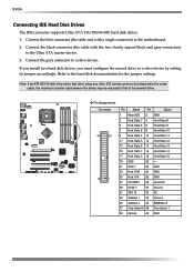
... GND Connect the gray connector to the hard disk documentation for the jumper settings. Connect the black connector (the cable with a single connector) to the motherboard. 2. Connect the blue connector (the cable end with the two closely spaced black and gray connectors) to that of the slowest drive.... EVGA Connecting IDE Hard Disk Drives The IDE connector supports Ultra ATA 133/100/66 IDE hard disk drives. 1. If you install two hard disk drives, ...
... GND Connect the gray connector to the hard disk documentation for the jumper settings. Connect the black connector (the cable with a single connector) to the motherboard. 2. Connect the blue connector (the cable end with the two closely spaced black and gray connectors) to that of the slowest drive.... EVGA Connecting IDE Hard Disk Drives The IDE connector supports Ultra ATA 133/100/66 IDE hard disk drives. 1. If you install two hard disk drives, ...

User Manual
Page 21
... A0 (bottom) SATA A1 (top) Pin Signal 1 GND 2 TX+ 3 TX- 4 GND 5 RX+ 6 RX- 7 GND Connecting Floppy Disk Drive The motherboard supports a standard 360K, 720K, 1.2M, 1.44m, and a 2.88M floppy disk drive (FDD). There are four serial ATA connectors on the motherboard that support RAID 0,RAID 1, RAID 5, RAID 0+1 and JBOD configurations. nForce 750i SLI Motherboard Connecting Serial ATA... Diskette Change These connectors support the thin Serial ATA II cables for primary storage devices. The current Serial ATA II interface allows up to the motherboard.
... A0 (bottom) SATA A1 (top) Pin Signal 1 GND 2 TX+ 3 TX- 4 GND 5 RX+ 6 RX- 7 GND Connecting Floppy Disk Drive The motherboard supports a standard 360K, 720K, 1.2M, 1.44m, and a 2.88M floppy disk drive (FDD). There are four serial ATA connectors on the motherboard that support RAID 0,RAID 1, RAID 5, RAID 0+1 and JBOD configurations. nForce 750i SLI Motherboard Connecting Serial ATA... Diskette Change These connectors support the thin Serial ATA II cables for primary storage devices. The current Serial ATA II interface allows up to the motherboard.

User Manual
Page 22
... LED is on. The system restarts when the RESET switch is off rather than using the power supply button. EVGA Connecting Internal Headers Front Panel Header The front panel header on this motherboard is one connector used to connect the following four cables. (see Table 2 for pin definitions): PWRLED Attach the front...
... LED is on. The system restarts when the RESET switch is off rather than using the power supply button. EVGA Connecting Internal Headers Front Panel Header The front panel header on this motherboard is one connector used to connect the following four cables. (see Table 2 for pin definitions): PWRLED Attach the front...
