User Guide
Page 3
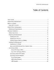
EVGA P55 LE Motherboard Table of Contents User's Guide ...1 EVGA P55 LE Motherboard 1 Before You Begin...7 Parts NOT in the Kit 7 EVGA P55 LE Motherboard 8 Motherboard Specifications 8 Hardware Installation 10 Safety Instructions 10 Preparing the Motherboard 11 Installing the CPU 11 Installing the CPU Fan 12 Installing System Memory (DIMMs 13 Installing the Motherboard 13 Installing the I/O Shield 14 Securing the Motherboard into a System Case 15 Connecting Cables...
EVGA P55 LE Motherboard Table of Contents User's Guide ...1 EVGA P55 LE Motherboard 1 Before You Begin...7 Parts NOT in the Kit 7 EVGA P55 LE Motherboard 8 Motherboard Specifications 8 Hardware Installation 10 Safety Instructions 10 Preparing the Motherboard 11 Installing the CPU 11 Installing the CPU Fan 12 Installing System Memory (DIMMs 13 Installing the Motherboard 13 Installing the I/O Shield 14 Securing the Motherboard into a System Case 15 Connecting Cables...
User Guide
Page 5
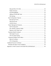
... Health Configure 37 H/W Health Function 37 CPU Fan Mode Setting 38 Frequency/Voltage Control Menu 38 Memory Configure 38 CPU Configuration 38 Installing Drivers and Software 39 Windows XP/Vista/7 Driver Installation 39 Appendix A. EVGA P55 LE Motherboard Allocate IRQ to PCI VGA 34 Palette Snooping 34 PCI IDE BusMaster 34 OffBoard PCI/ISA IDE... Boot Device Priority 35 Hard Disk Drives 35 CD/DVD Drives 36 Power Management Features 36 ACPI Configuration 36 SLP_S4# Min. POST Codes for the EVGA P55 LE Motherboard 40
... Health Configure 37 H/W Health Function 37 CPU Fan Mode Setting 38 Frequency/Voltage Control Menu 38 Memory Configure 38 CPU Configuration 38 Installing Drivers and Software 39 Windows XP/Vista/7 Driver Installation 39 Appendix A. EVGA P55 LE Motherboard Allocate IRQ to PCI VGA 34 Palette Snooping 34 PCI IDE BusMaster 34 OffBoard PCI/ISA IDE... Boot Device Priority 35 Hard Disk Drives 35 CD/DVD Drives 36 Power Management Features 36 ACPI Configuration 36 SLP_S4# Min. POST Codes for the EVGA P55 LE Motherboard 40
User Guide
Page 7
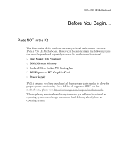
... CPU's on this motherboard, please visit http://www.evga.com/support/motherboard/. Parts NOT in a system case, you have an operating system. EVGA P55 LE Motherboard Before You Begin... However, it does not contain the following items that must be purchased separately to make the motherboard functional. Intel Socket 1156 Processor DDR3 System Memory Socket 1156...
... CPU's on this motherboard, please visit http://www.evga.com/support/motherboard/. Parts NOT in a system case, you have an operating system. EVGA P55 LE Motherboard Before You Begin... However, it does not contain the following items that must be purchased separately to make the motherboard functional. Intel Socket 1156 Processor DDR3 System Memory Socket 1156...
User Guide
Page 8
... systems: Supports Windows XP 32bit/64bit, Windows Vista 32bit/64bit, and Windows 7 32bit/64bit Intel P55 Express Chipset System Memory support Supports dual channel DDR3-1600+. EVGA P55 LE Motherboard Motherboard Specifications Size ATX form factor of DDR3 memory. USB 2.0 Ports Supports hot plug Fourteen USB 2.0 ports (Eight rear panel ports, six onboard USB...
... systems: Supports Windows XP 32bit/64bit, Windows Vista 32bit/64bit, and Windows 7 32bit/64bit Intel P55 Express Chipset System Memory support Supports dual channel DDR3-1600+. EVGA P55 LE Motherboard Motherboard Specifications Size ATX form factor of DDR3 memory. USB 2.0 Ports Supports hot plug Fourteen USB 2.0 ports (Eight rear panel ports, six onboard USB...
User Guide
Page 10
Hardware Installation This section will guide you through the installation of fire, electric shocks, and injury, always follow basic safety precautions. Remember to remove power off your computer by disconnecting the AC main source before removing or installing any equipment from/to the computer chassis. The topics covered in this section are: Preparing the motherboard Installing the CPU Installing the CPU fan Installing the memory Installing the motherboard Connecting cables Safety Instructions To reduce the risk of the motherboard.
Hardware Installation This section will guide you through the installation of fire, electric shocks, and injury, always follow basic safety precautions. Remember to remove power off your computer by disconnecting the AC main source before removing or installing any equipment from/to the computer chassis. The topics covered in this section are: Preparing the motherboard Installing the CPU Installing the CPU fan Installing the memory Installing the motherboard Connecting cables Safety Instructions To reduce the risk of the motherboard.
User Guide
Page 13
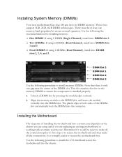
...Slot 1 DIMM Slot 4 DIMM Slot 3 Use the following the recommendations for DDR3 memory. There must be easier to make all the connections prior to this step or to secure the motherboard first. Align the memory module to the DIMM slot, and insert the module vertically into the DIMM slot.... Installing System Memory (DIMMs) Your new motherboard has four 240-pin slots for installing memory. One DIMM: If using 1 DIMM (Single Channel), install into: DIMM slot 1. Two DIMMs: If using 2 DIMMs (Dual Channel), ...
...Slot 1 DIMM Slot 4 DIMM Slot 3 Use the following the recommendations for DDR3 memory. There must be easier to make all the connections prior to this step or to secure the motherboard first. Align the memory module to the DIMM slot, and insert the module vertically into the DIMM slot.... Installing System Memory (DIMMs) Your new motherboard has four 240-pin slots for installing memory. One DIMM: If using 1 DIMM (Single Channel), install into: DIMM slot 1. Two DIMMs: If using 2 DIMMs (Dual Channel), ...
User Guide
Page 24
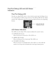
... system's status. POWER LED (Green): When the System is powered on: This LED is on. DIMM LED (Orange): When the Memory slot is functional: This LED is on. STANDBY LED (Blue): When the System is in Standby Mode: This LED is useful during troubleshooting situations.... It is on as long as the motherboard is receiving constant power. This Debug LED will remain on . This LED will also display current CPU temperatures after the system has fully booted into...
... system's status. POWER LED (Green): When the System is powered on: This LED is on. DIMM LED (Orange): When the Memory slot is functional: This LED is on. STANDBY LED (Blue): When the System is in Standby Mode: This LED is useful during troubleshooting situations.... It is on as long as the motherboard is receiving constant power. This Debug LED will remain on . This LED will also display current CPU temperatures after the system has fully booted into...
User Guide
Page 27
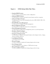
...; Hardware Health Configure Use this menu to view system vitals. Frequency/Voltage Control Use this menu to optimize system performance and configure clocks, voltages, memory timings, and more. Load Optimal Defaults Load default system settings. Discard Changes Use this command to abandon all setting changes and exit setup...
...; Hardware Health Configure Use this menu to view system vitals. Frequency/Voltage Control Use this menu to optimize system performance and configure clocks, voltages, memory timings, and more. Load Optimal Defaults Load default system settings. Discard Changes Use this command to abandon all setting changes and exit setup...
User Guide
Page 28
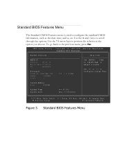
... Menu Use [+] or [-] to select a field. Use the + and - To go back to position the selector in the option you choose. CMOS Setup Utility - System Memory Size :4088MB System Time System Date [13:37:00] [Fri 07/16/2010] Move Enter:Select +/-/:Value F10:Save ESC:Exit F1:General Help F5...
... Menu Use [+] or [-] to select a field. Use the + and - To go back to position the selector in the option you choose. CMOS Setup Utility - System Memory Size :4088MB System Time System Date [13:37:00] [Fri 07/16/2010] Move Enter:Select +/-/:Value F10:Save ESC:Exit F1:General Help F5...

User Guide
Page 34
... the BIOS to inform the system that an ISA graphics device is recommended to leave this as Available. A setting of the memory block to reserve for legacy ISA devices. Reserved Memory Size This option allows you to specify the size of [Auto] works for reading or writing to IDE drives. DMA Channel...
... the BIOS to inform the system that an ISA graphics device is recommended to leave this as Available. A setting of the memory block to reserve for legacy ISA devices. Reserved Memory Size This option allows you to specify the size of [Auto] works for reading or writing to IDE drives. DMA Channel...

User Guide
Page 37
... System Temperature Sensor :34C/93F :48C/118F :34C/93F CPU Fan Speed Power Fan Speed Chassis Fan Speed :3264 RPM :1337 RPM :3864 RPM VCore Memory CPU VTT PCH +5V :1.337 V :1.481 V :1.021 V :1.031 V :4.961 V Help Item Enables Hardware Health Monitoring Device. Move Enter:Select +/-/:Value F10:Save ESC:Exit F1...
... System Temperature Sensor :34C/93F :48C/118F :34C/93F CPU Fan Speed Power Fan Speed Chassis Fan Speed :3264 RPM :1337 RPM :3864 RPM VCore Memory CPU VTT PCH +5V :1.337 V :1.481 V :1.021 V :1.031 V :4.961 V Help Item Enables Hardware Health Monitoring Device. Move Enter:Select +/-/:Value F10:Save ESC:Exit F1...

User Guide
Page 38
...the settings. CPU Fan Mode Setting This function allows change of advanced memory timings, including memory frequency and memory timings. AwardBIOS CMOS Setup Utility Frequency/Voltage Control Memory Configure CPU Configuration [Press Enter] [Press Enter] CPU ...Multiplier Setting CPU Frequency Setting PCIE Frequency Setting [20] [133] [100] EVGA VDroop Control [With VDroop] Current CPU VCore : 1.33700V CPU VCore [...
...the settings. CPU Fan Mode Setting This function allows change of advanced memory timings, including memory frequency and memory timings. AwardBIOS CMOS Setup Utility Frequency/Voltage Control Memory Configure CPU Configuration [Press Enter] [Press Enter] CPU ...Multiplier Setting CPU Frequency Setting PCIE Frequency Setting [20] [133] [100] EVGA VDroop Control [With VDroop] Current CPU VCore : 1.33700V CPU VCore [...

User Guide
Page 41
... System Management interrupt vector Uncompress and initialize BIOS module Initialize devices primary Initialize devices secondary Initialize output devices Allocate memory for ADM module Initialize silent boot module Display sign-on message Initialize USB controller Initialize DMAC-1 & DMAC-2 Initialize real... time clock Test system memory Initialization of chipset registers Detect coprocessor Update CMOS memory size Initialize NUM-LOCK Initialize Int-13 Initialize IPL devices Generate and write contents of ESCD Log...
... System Management interrupt vector Uncompress and initialize BIOS module Initialize devices primary Initialize devices secondary Initialize output devices Allocate memory for ADM module Initialize silent boot module Display sign-on message Initialize USB controller Initialize DMAC-1 & DMAC-2 Initialize real... time clock Test system memory Initialization of chipset registers Detect coprocessor Update CMOS memory size Initialize NUM-LOCK Initialize Int-13 Initialize IPL devices Generate and write contents of ESCD Log...
User Guide
Page 42
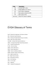
... Disk Controller FSB - GHz - Alternate Frame Rendering APIC - Basic Input Output System CD-ROM - Complementary Metal-Oxide Semiconductor CPU - Dynamic random access memory DVD - Digital Video Interface FDC - Graphics Processing Unit Advanced Configuration and Power Interface AFR - Digital Versatile Disc DVI - Front Side Bus FTW - ...19 boot End of POST initialization Save system context for ACPI Pass control to OS Show CPU Temp (if enabled) EVGA Glossary of Terms ACPI - Compact Disc Read-Only Memory CMOS - Dry Ice Cooling DDR2 - Double Data Rate 2 DDR3 -
... Disk Controller FSB - GHz - Alternate Frame Rendering APIC - Basic Input Output System CD-ROM - Complementary Metal-Oxide Semiconductor CPU - Dynamic random access memory DVD - Digital Video Interface FDC - Graphics Processing Unit Advanced Configuration and Power Interface AFR - Digital Versatile Disc DVI - Front Side Bus FTW - ...19 boot End of POST initialization Save system context for ACPI Pass control to OS Show CPU Temp (if enabled) EVGA Glossary of Terms ACPI - Compact Disc Read-Only Memory CMOS - Dry Ice Cooling DDR2 - Double Data Rate 2 DDR3 -