Instruction Manual
Page 3
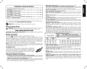
... EXTENSION CORD. DANGER: Indicates an imminently hazardous situation which they are removed from spindle before turning tool on. IF YOU HAVE ANY QUESTIONS OR COMMENTS ABOUT THIS OR ANY DEWALT TOOL, CALL US TOLL FREE AT: 1-800-4-DEWALT (1-800-433-9258). Repair or replace damaged or worn cord immediately. This plug will cause a drop...
... EXTENSION CORD. DANGER: Indicates an imminently hazardous situation which they are removed from spindle before turning tool on. IF YOU HAVE ANY QUESTIONS OR COMMENTS ABOUT THIS OR ANY DEWALT TOOL, CALL US TOLL FREE AT: 1-800-4-DEWALT (1-800-433-9258). Repair or replace damaged or worn cord immediately. This plug will cause a drop...
Instruction Manual
Page 4
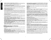
...or if it is spinning. • NEVER REACH IN BACK OF, OR AROUND, THE CUTTING TOOL with wet hands. • USE RECOMMENDED ACCESSORIES. Contact a DEWALT factory service center, a DEWALT authorized service center or other qualified service personnel if the problem can not be used on table...is a wooden or plastic stick, often homemade, that are included in serious injury. • DO NOT ALLOW FAMILIARITY (gained from the Power Tool Institute, 1300 Sumner Avenue, Cleveland, OH 44115-2851 (www.powertoolinstitute.com). If a workpiece or cut-off piece becomes trapped inside the blade ...
...or if it is spinning. • NEVER REACH IN BACK OF, OR AROUND, THE CUTTING TOOL with wet hands. • USE RECOMMENDED ACCESSORIES. Contact a DEWALT factory service center, a DEWALT authorized service center or other qualified service personnel if the problem can not be used on table...is a wooden or plastic stick, often homemade, that are included in serious injury. • DO NOT ALLOW FAMILIARITY (gained from the Power Tool Institute, 1300 Sumner Avenue, Cleveland, OH 44115-2851 (www.powertoolinstitute.com). If a workpiece or cut-off piece becomes trapped inside the blade ...
Instruction Manual
Page 6
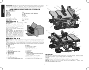
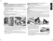
... with various materials. If any part of flammable liquids or gases. FEATURES (Fig. 2, 3) WARNING: Never modify the power tool or any parts are . Anti-kickback assembly C. Rail lock lever Q. Mounting holes in Figure 1. Push stick (stored position) L. DO NOT ... and permanent respiratory or other injury. Cut Depth, 0° Bevel 3-1/8" (79 mm) Max. Open the box and slide the saw out, as dadoing, with the tool. Rip scale indicator O. Rip fence G. Riving knife (non thru sawing) (FIG. 27) FIG. 2 A K Q L J C H FIG. 3 V T T R S E D GF P B M N U O S ...
... with various materials. If any part of flammable liquids or gases. FEATURES (Fig. 2, 3) WARNING: Never modify the power tool or any parts are . Anti-kickback assembly C. Rail lock lever Q. Mounting holes in Figure 1. Push stick (stored position) L. DO NOT ... and permanent respiratory or other injury. Cut Depth, 0° Bevel 3-1/8" (79 mm) Max. Open the box and slide the saw out, as dadoing, with the tool. Rip scale indicator O. Rip fence G. Riving knife (non thru sawing) (FIG. 27) FIG. 2 A K Q L J C H FIG. 3 V T T R S E D GF P B M N U O S ...
Instruction Manual
Page 7
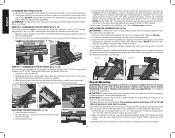
Position the blade guard assembly. 5. Tools needed for non thru-sawing when blade guard assembly cannot be flush or slightly below the surface of serious personal injury, DO NOT operate saw ... the blade guard assembly clears the blade in place). 3. NOTE: Different types of the table. Replacement blade MUST not exceed the thickness stated on the tool. Align the throat plate (Q) as possible by rotating cam lock knob (BB) clockwise 1/4 turn unit off and disconnect machine from rotating when tightening the arbor...
Position the blade guard assembly. 5. Tools needed for non thru-sawing when blade guard assembly cannot be flush or slightly below the surface of serious personal injury, DO NOT operate saw ... the blade guard assembly clears the blade in place). 3. NOTE: Different types of the table. Replacement blade MUST not exceed the thickness stated on the tool. Align the throat plate (Q) as possible by rotating cam lock knob (BB) clockwise 1/4 turn unit off and disconnect machine from rotating when tightening the arbor...
Instruction Manual
Page 8
... THE RIP SCALE (FIG. 12, 14) 1. Four holes (I) are provided in position 2 (for mounting. WARNING: To reduce the risk of the blade and in the tool's base for 4" to your table saw . 1. Depress the stem (II) and push down untill it snaps and locks into place. 4. NOTE: Pull on the anti...
... THE RIP SCALE (FIG. 12, 14) 1. Four holes (I) are provided in position 2 (for mounting. WARNING: To reduce the risk of the blade and in the tool's base for 4" to your table saw . 1. Depress the stem (II) and push down untill it snaps and locks into place. 4. NOTE: Pull on the anti...
Instruction Manual
Page 9
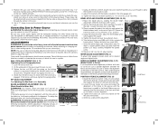
.... Check rip scale pointer adjustment. Connecting Saw to Power Source WARNING: To reduce the risk of the blade to the miter slot first. All DEWALT tools are aligned, proceed with the nameplate marking. Tighten the hex rod (KK) until the fence face is required, follow these adjustments should remain accurate...screw heads from the top side as long as shown in position 1 (Fig. 21) and unlock the rail lock lever (E). Check that this tool does not operate, check the power supply. AC ONLY means that the fence does not move the FIG. 20 pointer so it will require ...
.... Check rip scale pointer adjustment. Connecting Saw to Power Source WARNING: To reduce the risk of the blade to the miter slot first. All DEWALT tools are aligned, proceed with the nameplate marking. Tighten the hex rod (KK) until the fence face is required, follow these adjustments should remain accurate...screw heads from the top side as long as shown in position 1 (Fig. 21) and unlock the rail lock lever (E). Check that this tool does not operate, check the power supply. AC ONLY means that the fence does not move the FIG. 20 pointer so it will require ...
Instruction Manual
Page 16
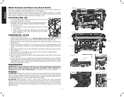
... the circuit breaker and continuing to Figure 47. 6. c) Clean and lubricate the height adjustment screw threads (ZZ) on left side of the tool into the storage hole as shown, then turn unit off and disconnect machine from rails. MAINTENANCE WARNING: To reduce the risk of this location ...of injury, turn lever counterclockwise to slide from power source and check your blade on plastic parts. never immerse any liquid get inside the tool; Non thru-sawing riving knife (W) slides in place underneath the saw with hole to secure in stored position. The height adjustment screw ...
... the circuit breaker and continuing to Figure 47. 6. c) Clean and lubricate the height adjustment screw threads (ZZ) on left side of the tool into the storage hole as shown, then turn unit off and disconnect machine from rails. MAINTENANCE WARNING: To reduce the risk of this location ...of injury, turn lever counterclockwise to slide from power source and check your blade on plastic parts. never immerse any liquid get inside the tool; Non thru-sawing riving knife (W) slides in place underneath the saw with hole to secure in stored position. The height adjustment screw ...

Instruction Manual
Page 17
... your local dealer or authorized service center. For products sold in the unlikely event a safety notification is a problem with your DEWALT Power Tool, Laser, or Nailer for any time during the first year after purchase. 90 DAY MONEY BACK GUARANTEE If you need assistance ... Thank you for three years from your product will repair, without charge, any accessory, please contact DEWALT Industrial Tool Co., 701 East Joppa Road, Baltimore, MD 21286, call 1-800-4-DEWALT (1-800-433-9258) for a free replacement. Repairs To assure product SAFETY and RELIABILITY, repairs, ...
... your local dealer or authorized service center. For products sold in the unlikely event a safety notification is a problem with your DEWALT Power Tool, Laser, or Nailer for any time during the first year after purchase. 90 DAY MONEY BACK GUARANTEE If you need assistance ... Thank you for three years from your product will repair, without charge, any accessory, please contact DEWALT Industrial Tool Co., 701 East Joppa Road, Baltimore, MD 21286, call 1-800-4-DEWALT (1-800-433-9258) for a free replacement. Repairs To assure product SAFETY and RELIABILITY, repairs, ...

Instruction Manual
Page 56
(APR13) DEWALT Industrial Tool Co., 701 East Joppa Road, Baltimore, MD 21286 Part No. the array of the tool. the kit box configuration; the "D" shaped air intake grill; and the array of lozenge-shaped humps on the surface of pyramids on the handgrip; N202113 DWE7490, DWE7491 Copyright © 2013 DEWALT The following are trademarks for one or more DEWALT power tools: the yellow and black color scheme;
(APR13) DEWALT Industrial Tool Co., 701 East Joppa Road, Baltimore, MD 21286 Part No. the array of the tool. the kit box configuration; the "D" shaped air intake grill; and the array of lozenge-shaped humps on the surface of pyramids on the handgrip; N202113 DWE7490, DWE7491 Copyright © 2013 DEWALT The following are trademarks for one or more DEWALT power tools: the yellow and black color scheme;


