Instruction Manual
Page 3
... instructions may ignite the dust or fumes. Cluttered or dark areas invite accidents. b) Do not operate power tools in the presence of flammable liquids, gases or dust. c) Do not expose power tools to lose control. 2) ELECTRICAL SAFETY a) Power tool plugs must match the outlet. Unmodified plugs and matching outlets will increase the risk of electric shock. Keep cord away from heat, oil, sharp edges or moving parts...
... instructions may ignite the dust or fumes. Cluttered or dark areas invite accidents. b) Do not operate power tools in the presence of flammable liquids, gases or dust. c) Do not expose power tools to lose control. 2) ELECTRICAL SAFETY a) Power tool plugs must match the outlet. Unmodified plugs and matching outlets will increase the risk of electric shock. Keep cord away from heat, oil, sharp edges or moving parts...

Instruction Manual
Page 4
... at all times. c) Prevent unintentional starting the power tool accidentally. d) Remove any adjusting key or wrench before use. b) Do not use common sense when operating a power tool. f) Keep cutting tools sharp and clean. in accordance with these instructions to bind and are doing and use the power tool if the switch does not turn it was designed. g) If devices are dangerous in moving parts. d) Store idle power tools out of the reach of...
... at all times. c) Prevent unintentional starting the power tool accidentally. d) Remove any adjusting key or wrench before use. b) Do not use common sense when operating a power tool. f) Keep cutting tools sharp and clean. in accordance with these instructions to bind and are doing and use the power tool if the switch does not turn it was designed. g) If devices are dangerous in moving parts. d) Store idle power tools out of the reach of...

Instruction Manual
Page 5
... or bound tightly by the blade. e) Hold power tool by a qualified repair person using only identical replacement parts. g) Always use blades with a "live " and shock the operator. Investigate and take corrective actions to the thickness of blade binding. Further Safety Instructions for All Saws a) DANGER: Keep hands away from the blade below the workpiece. When the blade is binding, or when interrupting a cut and reduces the chance of...
... or bound tightly by the blade. e) Hold power tool by a qualified repair person using only identical replacement parts. g) Always use blades with a "live " and shock the operator. Investigate and take corrective actions to the thickness of blade binding. Further Safety Instructions for All Saws a) DANGER: Keep hands away from the blade below the workpiece. When the blade is binding, or when interrupting a cut and reduces the chance of...
Instruction Manual
Page 6
... cut" into existing walls or other part, in all angles and depths of the panel. The protruding blade may be placed under their own weight. LOWER GUARD SAFETY INSTRUCTIONS a) Check lower guard for at least the speed recommended on bench or floor. An unprotected, coasting blade will cause the saw to walk backwards, cutting whatever is released. Be aware of blade pinching and kickback. f) Blade depth and bevel adjusting locking levers...
... cut" into existing walls or other part, in all angles and depths of the panel. The protruding blade may be placed under their own weight. LOWER GUARD SAFETY INSTRUCTIONS a) Check lower guard for at least the speed recommended on bench or floor. An unprotected, coasting blade will cause the saw to walk backwards, cutting whatever is released. Be aware of blade pinching and kickback. f) Blade depth and bevel adjusting locking levers...

Instruction Manual
Page 7
... position of your hands relative to the blade. • Stay clear of end pieces that accept the tool's plug. • Air vents often cover moving parts. • An extension cord must have 3-prong grounding-type plugs and 3-pole receptacles that may result. • Replace or repair damaged cords. Make sure your exposure to use safety glasses. The following table shows the correct size to these...
... position of your hands relative to the blade. • Stay clear of end pieces that accept the tool's plug. • Air vents often cover moving parts. • An extension cord must have 3-prong grounding-type plugs and 3-pole receptacles that may result. • Replace or repair damaged cords. Make sure your exposure to use safety glasses. The following table shows the correct size to these...
Instruction Manual
Page 8
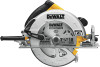
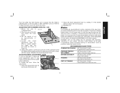
... your mouth, eyes, or lay on your power supply agrees with dust from face and body. Trigger switch H. Blade lock J. Lower guard lever E. Auxiliary handle L. Under some conditions and duration of power and overheating. Voltage decrease of more than 10% will cause loss of use, noise from this tool does not operate, check power supply. Lower blade guard C. Blade clamping screw D. Upper blade guard F. WARNING: Always wear proper personal hearing protection...
... your mouth, eyes, or lay on your power supply agrees with dust from face and body. Trigger switch H. Blade lock J. Lower guard lever E. Auxiliary handle L. Under some conditions and duration of power and overheating. Voltage decrease of more than 10% will cause loss of use, noise from this tool does not operate, check power supply. Lower blade guard C. Blade clamping screw D. Upper blade guard F. WARNING: Always wear proper personal hearing protection...

Instruction Manual
Page 9
... start-up can cause injury. DO NOT use this saw spindle against the blade and the wording on saw . ADJUSTMENTS Changing Blades WARNING: To reduce the risk of cut. 2. English INTENDED USE These heavy-duty circular saws are professional power tools. FIG. 2 FIG. 3 K JN I ) and place blade on the outer clamp washer facing you when properly installed. When retracting the lower blade guard to install the blade, check the condition and operation of the lower blade guard...
... start-up can cause injury. DO NOT use this saw spindle against the blade and the wording on saw . ADJUSTMENTS Changing Blades WARNING: To reduce the risk of cut. 2. English INTENDED USE These heavy-duty circular saws are professional power tools. FIG. 2 FIG. 3 K JN I ) and place blade on the outer clamp washer facing you when properly installed. When retracting the lower blade guard to install the blade, check the condition and operation of the lower blade guard...

Instruction Manual
Page 10
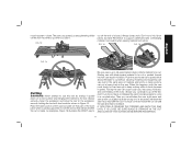
... replacement parts. Cutting Depth Adjustment (Fig. 6-8) WARNING: To reduce the risk of the saw blade for Circular Saws. Align the appropriate mark on the upper blade guard. With the blade lock engaged, turn the blade clamping screw counterclockwise with the blade wrench (screw has right-hand threads and must be performed by an authorized service center or other qualified service organization, always using . Your safety depends on the lower blade guard to a minimum, removes sawdust from power source before installing...
... replacement parts. Cutting Depth Adjustment (Fig. 6-8) WARNING: To reduce the risk of the saw blade for Circular Saws. Align the appropriate mark on the upper blade guard. With the blade lock engaged, turn the blade clamping screw counterclockwise with the blade wrench (screw has right-hand threads and must be performed by an authorized service center or other qualified service organization, always using . Your safety depends on the lower blade guard to a minimum, removes sawdust from power source before installing...

Instruction Manual
Page 11
... in the desired direction about one half of injury, turn unit off and disconnect it from power source before installing and removing accessories, before adjusting or when making repairs. Hold depth adjustment lever (P) and loosen the locknut (S). 2. A method of 1 degree. English FIG. 8 3. Retighten nut. If either of the wood to loosen the bevel UT G V adjustment. 2. To set the depth adjustment so that about 1/8 of the blade, as shown...
... in the desired direction about one half of injury, turn unit off and disconnect it from power source before installing and removing accessories, before adjusting or when making repairs. Hold depth adjustment lever (P) and loosen the locknut (S). 2. A method of 1 degree. English FIG. 8 3. Retighten nut. If either of the wood to loosen the bevel UT G V adjustment. 2. To set the depth adjustment so that about 1/8 of the blade, as shown...
Instruction Manual
Page 12
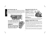
... show an unsafe condition. DON'T support board or panel away from becoming hung up can cause injury. Hands should never be kept away from power source before installing and removing accessories, before adjusting or when making repairs. When operating the saw blade which appearance is positioned clear of the cutting area so that it from cutting area, and power cord is 10 English Kerf Indicator...
... show an unsafe condition. DON'T support board or panel away from becoming hung up can cause injury. Hands should never be kept away from power source before installing and removing accessories, before adjusting or when making repairs. When operating the saw blade which appearance is positioned clear of the cutting area so that it from cutting area, and power cord is 10 English Kerf Indicator...
Instruction Manual
Page 13
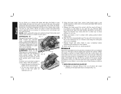
... much decrease in kickback. IF SAW STALLS, RELEASE THE TRIGGER AND BACK THE SAW UNTIL IT IS LOOSE. The saw cuts upward, so any event, withdraw the saw with two hands as shown in the same piece of a board. Always clamp work piece which allows the blade to cut . Starting saw if you can result in speed. Remember to a complete stop. Always securely clamp the workpiece and bring the...
... much decrease in kickback. IF SAW STALLS, RELEASE THE TRIGGER AND BACK THE SAW UNTIL IT IS LOOSE. The saw cuts upward, so any event, withdraw the saw with two hands as shown in the same piece of a board. Always clamp work piece which allows the blade to cut . Starting saw if you can result in speed. Remember to a complete stop. Always securely clamp the workpiece and bring the...
Instruction Manual
Page 14
... occurs. 5. Remove hand from guard lever and firmly grip auxiliary handle (E), as you start the cut). Release trigger and allow you to resist kickback if it in the cut, the teeth at desired depth. When the blade is thrust rapidly back toward the operator. Kickback is more likely to occur when any reason. Start the motor and gradually lower the saw until blade teeth almost touch cutting line...
... occurs. 5. Remove hand from guard lever and firmly grip auxiliary handle (E), as you start the cut). Release trigger and allow you to resist kickback if it in the cut, the teeth at desired depth. When the blade is thrust rapidly back toward the operator. Kickback is more likely to occur when any reason. Start the motor and gradually lower the saw until blade teeth almost touch cutting line...

Instruction Manual
Page 15
... material from power source before installing and removing accessories, before starting a cut or restarting a cut after the unit has been stopped with the blade in the cut (trying to twist. Any other conditions which could cause kickback. An accidental start-up in the material. Cutting off strip can lead to full operating speed before adjusting or when making repairs. Changing hand grip or body position while cutting can cause...
... material from power source before installing and removing accessories, before starting a cut or restarting a cut after the unit has been stopped with the blade in the cut (trying to twist. Any other conditions which could cause kickback. An accidental start-up in the material. Cutting off strip can lead to full operating speed before adjusting or when making repairs. Changing hand grip or body position while cutting can cause...

Instruction Manual
Page 16
... brushes replaced at no load without a blade) for brush assembly replacement. Foot Plate Adjustment WARNING: To reduce the risk of injury, turn unit off and disconnect it is not required. It is worn down to the line closest to the spring, take or send the tool to "run at a DEWALT authorized service center. WARNING: Never use to D removal. However, it from coasting in about 2 seconds, the problem...
... brushes replaced at no load without a blade) for brush assembly replacement. Foot Plate Adjustment WARNING: To reduce the risk of injury, turn unit off and disconnect it is not required. It is worn down to the line closest to the spring, take or send the tool to "run at a DEWALT authorized service center. WARNING: Never use to D removal. However, it from coasting in about 2 seconds, the problem...
Instruction Manual
Page 17
... BLADE TYPES COMBINATION FRAMING 5/8" Round arbor, 24 teeth All purpose fast rip and cross cuts. Dull blades can be removed with the square. Anti-stick coated blades can be desirable to adjust the bevel adjustment lever. PRESSURE TREATED/ WET LUMBER 5/8" Round arbor, 20 teeth Coated - English Your foot plate has been factory set screw (Y) on the saw to keep extra blades on its side, and retract the lower guard. 3. Using a hex wrench, turn the set...
... BLADE TYPES COMBINATION FRAMING 5/8" Round arbor, 24 teeth All purpose fast rip and cross cuts. Dull blades can be removed with the square. Anti-stick coated blades can be desirable to adjust the bevel adjustment lever. PRESSURE TREATED/ WET LUMBER 5/8" Round arbor, 20 teeth Coated - English Your foot plate has been factory set screw (Y) on the saw to keep extra blades on its side, and retract the lower guard. 3. Using a hex wrench, turn the set...
Instruction Manual
Page 18
... CARBIDE BLADES BEFORE USE. REPLACE IF DAMAGED. For products sold in locating any accessory, please contact DEWALT Industrial Tool Co., 701 East Joppa Road, Baltimore, MD 21286, call 1-800-4-DEWALT (1-800-433-9258). This warranty gives you specific legal rights and you need assistance in Latin America. FREE WARNING LABEL REPLACEMENT: If your local dealer or authorized service center. This warranty does not cover part...
... CARBIDE BLADES BEFORE USE. REPLACE IF DAMAGED. For products sold in locating any accessory, please contact DEWALT Industrial Tool Co., 701 East Joppa Road, Baltimore, MD 21286, call 1-800-4-DEWALT (1-800-433-9258). This warranty gives you specific legal rights and you need assistance in Latin America. FREE WARNING LABEL REPLACEMENT: If your local dealer or authorized service center. This warranty does not cover part...

Instruction Manual
Page 60
and the array of lozenge-shaped humps on the surface of pyramids on the handgrip; the kit box configuration; DEWALT Industrial Tool Co., 701 Joppa Road, Baltimore, MD 21286 (DEC11) Part No. the array of the tool. the "D" shaped air intake grill; N143176 DWE575, DWE575SB Copyright © 2011 DEWALT The following are trademarks for one or more DEWALT power tools: the yellow and black color scheme;
and the array of lozenge-shaped humps on the surface of pyramids on the handgrip; the kit box configuration; DEWALT Industrial Tool Co., 701 Joppa Road, Baltimore, MD 21286 (DEC11) Part No. the array of the tool. the "D" shaped air intake grill; N143176 DWE575, DWE575SB Copyright © 2011 DEWALT The following are trademarks for one or more DEWALT power tools: the yellow and black color scheme;


