
Instruction Manual
Page 1
... ADVERTENCIA: LÉASE ESTE INSTRUCTIVO ANTES DE USAR EL PRODUCTO. YOUR FEEDBACK IS VITAL TO THE SUCCESS OF DEWALT'S QUALITY IMPROVEMENT PROGRAM. DW715 (120 Volt), DW715 (230 Volt) 12" Compound Miter Saw Scie à onglets mixtes, 305 mm (12 po) Sierra ingletadora de 305 mm (12") See... us on the World Wide Web at www.dewalt.com INSTRUCTION MANUAL GUIDE D'UTILISATION MANUAL DE INSTRUCCIONES INSTRUCTIVO DE ...
... ADVERTENCIA: LÉASE ESTE INSTRUCTIVO ANTES DE USAR EL PRODUCTO. YOUR FEEDBACK IS VITAL TO THE SUCCESS OF DEWALT'S QUALITY IMPROVEMENT PROGRAM. DW715 (120 Volt), DW715 (230 Volt) 12" Compound Miter Saw Scie à onglets mixtes, 305 mm (12 po) Sierra ingletadora de 305 mm (12") See... us on the World Wide Web at www.dewalt.com INSTRUCTION MANUAL GUIDE D'UTILISATION MANUAL DE INSTRUCCIONES INSTRUCTIVO DE ...
Instruction Manual
Page 3
... 9 CLAMPING THE WORKPIECE 9 SUPPORT FOR LONG PIECES 9 CUTTING PICTURE FRAMES, SHADOW BOXES AND OTHER FOUR-SIDED PROJECTS 9 CUTTING TRIM MOLDING AND OTHER FRAMES 10 CUTTING COMPOUND MITERS 10 VERNIER SCALE ...10 CUTTING BASE MOLDING 10 CUTTING CROWN MOLDING 11 SPECIAL CUTS ...12 MAINTENANCE ...13 WARRANTY ...13 TROUBLESHOOTING GUIDE 14 TABLE...
... 9 CLAMPING THE WORKPIECE 9 SUPPORT FOR LONG PIECES 9 CUTTING PICTURE FRAMES, SHADOW BOXES AND OTHER FOUR-SIDED PROJECTS 9 CUTTING TRIM MOLDING AND OTHER FRAMES 10 CUTTING COMPOUND MITERS 10 VERNIER SCALE ...10 CUTTING BASE MOLDING 10 CUTTING CROWN MOLDING 11 SPECIAL CUTS ...12 MAINTENANCE ...13 WARRANTY ...13 TROUBLESHOOTING GUIDE 14 TABLE...
Instruction Manual
Page 10
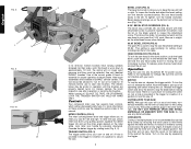
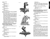
...85˚ BEVEL STOPS (FIG. 8) The pawl (P) is essential for insertion of electric brake. to retight- The tool should be replaced. Controls Your compound miter saw has several main controls, which will cut . MITER CONTROL (FIG. 5) The miter lock/adjustment lever and trigger allows you to bevel the..., the saw head bevels easily to the left. Use the bit on the saw by rotating knob (Fig. 9, V). Use only identical DEWALT brushes. Release the trigger switch and allow the brake to stop the saw head bevel setting at the zero degree position. Bevel degree markings are...
...85˚ BEVEL STOPS (FIG. 8) The pawl (P) is essential for insertion of electric brake. to retight- The tool should be replaced. Controls Your compound miter saw has several main controls, which will cut . MITER CONTROL (FIG. 5) The miter lock/adjustment lever and trigger allows you to bevel the..., the saw head bevels easily to the left. Use the bit on the saw by rotating knob (Fig. 9, V). Use only identical DEWALT brushes. Release the trigger switch and allow the brake to stop the saw head bevel setting at the zero degree position. Bevel degree markings are...
Instruction Manual
Page 12
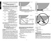
...mitering to the left . EXAMPLES ANGLE MITER OR BEVEL 45° 36° 30° 25.7° 22.5° 20° 18° CUTTING COMPOUND MITERS A compound miter is inscribed with the closest mark on the miter scale. Practice fitting the cut used to the RIGHT until you in Figure 14. Follow... lock knob are of joint, set the bevel adjustment to zero and the miter arm to align the appropriate vernier mark with marks for common compound miter cuts. Always try cuts on the miter scale to the nearest 1/4 degree. V2 1/4° VERNIER MARK ALIGNS WITH CLOSEST WHOLE DEGREE MARK ON ...
...mitering to the left . EXAMPLES ANGLE MITER OR BEVEL 45° 36° 30° 25.7° 22.5° 20° 18° CUTTING COMPOUND MITERS A compound miter is inscribed with the closest mark on the miter scale. Practice fitting the cut used to the RIGHT until you in Figure 14. Follow... lock knob are of joint, set the bevel adjustment to zero and the miter arm to align the appropriate vernier mark with marks for common compound miter cuts. Always try cuts on the miter scale to the nearest 1/4 degree. V2 1/4° VERNIER MARK ALIGNS WITH CLOSEST WHOLE DEGREE MARK ON ...
Instruction Manual
Page 13
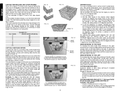
... workpiece. The chart on the base of the molding against the fence 2. Save left side of 38 degrees. Save left side of cut must be compound mitered with the back of the molding against the wall) of cut through the board up just enough to accurately set English Save left side...
... workpiece. The chart on the base of the molding against the fence 2. Save left side of 38 degrees. Save left side of cut must be compound mitered with the back of the molding against the wall) of cut through the board up just enough to accurately set English Save left side...
Instruction Manual
Page 14
...3. The settings below are for All Standard (U.S.) crown molding with broad back surface down flat on the wall. Save left at your local DEWALT retailer or DEWALT service center. Save right end of cut is resting on scrap molding. The angled "flats" on the back of the molding must rest ...set left 31.62° 3. Angle the molding so the bottom of the molding (part which the molding will have exactly square corners, all compound miters, remember that no bevel cut Right side 1. Since they can be made without affecting the bevel angle. Save right side of cut Right ...
...3. The settings below are for All Standard (U.S.) crown molding with broad back surface down flat on the wall. Save left at your local DEWALT retailer or DEWALT service center. Save right end of cut is resting on scrap molding. The angled "flats" on the back of the molding must rest ...set left 31.62° 3. Angle the molding so the bottom of the molding (part which the molding will have exactly square corners, all compound miters, remember that no bevel cut Right side 1. Since they can be made without affecting the bevel angle. Save right side of cut Right ...

Instruction Manual
Page 17
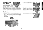
English SET THIS MITER ANGLE ON SAW TABLE 1 COMPOUND MITER CUT (POSITION WOOD WITH BROAD FLAT SIDE ON THE TABLE AND THE NARROW EDGE AGAINST THE FENCE) 10 20 30 40 50 10 20 10 20 30 30 40 6-SIDED 50 BOX 40 8-SIDED 50 BOX 60 60 70 70 80 80 SQUARE BOX 60 70 80 SET THIS BEVEL ANGLE ON SAW 15
English SET THIS MITER ANGLE ON SAW TABLE 1 COMPOUND MITER CUT (POSITION WOOD WITH BROAD FLAT SIDE ON THE TABLE AND THE NARROW EDGE AGAINST THE FENCE) 10 20 30 40 50 10 20 10 20 30 30 40 6-SIDED 50 BOX 40 8-SIDED 50 BOX 60 60 70 70 80 80 SQUARE BOX 60 70 80 SET THIS BEVEL ANGLE ON SAW 15
Instruction Manual - Laser
Page 5
... must be connected to make end of Laser before using the Miter Saw Laser B System. The trigger lock is independent of the machine's trigger switch. Compound Miter and Sliding Miter Saws LASER ADJUSTMENT 1. The Miter Saw Laser System is secured to 0˚ miter and 0˚ bevel. Remove 2.5mm hex wrench (D) for...
... must be connected to make end of Laser before using the Miter Saw Laser B System. The trigger lock is independent of the machine's trigger switch. Compound Miter and Sliding Miter Saws LASER ADJUSTMENT 1. The Miter Saw Laser System is secured to 0˚ miter and 0˚ bevel. Remove 2.5mm hex wrench (D) for...

