
Instruction Manual
Page 3
... ADJUSTMENT 6 MITER POINTER ADJUSTMENT 7 BEVEL SQUARE TO TABLE 7 BEVEL POINTER ...7 BEVEL STOP ADJUSTMENT 7 FENCE ADJUSTMENT 7 AUTOMATIC ELECTRIC BRAKE 7 GUARD ACTUATION AND VISIBILITY 7 MITER LOCK ADJUSTMENT 7 BRUSHES...7 CONTROLS ...8 OPERATION ...8 SWITCH ...8 CUTTING WITH YOUR SAW 8 CROSSCUTS...8 BEVEL CUTS ...9 QUALITY OF CUT ...9 BODY AND HAND POSITION 9 CLAMPING THE WORKPIECE 9 SUPPORT FOR LONG PIECES 9 CUTTING...
... ADJUSTMENT 6 MITER POINTER ADJUSTMENT 7 BEVEL SQUARE TO TABLE 7 BEVEL POINTER ...7 BEVEL STOP ADJUSTMENT 7 FENCE ADJUSTMENT 7 AUTOMATIC ELECTRIC BRAKE 7 GUARD ACTUATION AND VISIBILITY 7 MITER LOCK ADJUSTMENT 7 BRUSHES...7 CONTROLS ...8 OPERATION ...8 SWITCH ...8 CUTTING WITH YOUR SAW 8 CROSSCUTS...8 BEVEL CUTS ...9 QUALITY OF CUT ...9 BODY AND HAND POSITION 9 CLAMPING THE WORKPIECE 9 SUPPORT FOR LONG PIECES 9 CUTTING...
Instruction Manual
Page 9
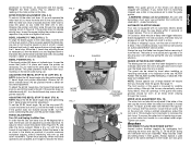
... don't forget to obtain an accurate adjustment. To ensure the miter lock is louvered for clearance. Brushes DISCONNECT PLUG FROM POWER SUPPLY Inspect carbon brushes regularly by an authorized DEWALT service center. Ensure the bevel override levers (N) are pushed inward to relocate the fence. To set... cutting. The front section of a tooth. GUARD ACTUATION AND VISIBILITY The blade guard on the bevel scale during use eye protection. Keep brushes clean and sliding freely in the down . Retighten the three screws. BEVEL SQUARE TO TABLE (FIG. 2, 7) To align the blade...
... don't forget to obtain an accurate adjustment. To ensure the miter lock is louvered for clearance. Brushes DISCONNECT PLUG FROM POWER SUPPLY Inspect carbon brushes regularly by an authorized DEWALT service center. Ensure the bevel override levers (N) are pushed inward to relocate the fence. To set... cutting. The front section of a tooth. GUARD ACTUATION AND VISIBILITY The blade guard on the bevel scale during use eye protection. Keep brushes clean and sliding freely in the down . Retighten the three screws. BEVEL SQUARE TO TABLE (FIG. 2, 7) To align the blade...
Instruction Manual
Page 10
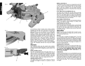
... THE TRIGGER SWITCH ON. English FIG. 8 L FIG. 9 FIG. 10 N O V W U BEVEL LOCK (FIG. 8) The bevel lock knob (L) allows you to seat new brushes. R 0˚/45˚ BEVEL STOP OVERRIDES (FIG. 8) The bevel stop the saw by pulling upward, squeeze the detent trigger (K) and set the miter angle desired...the down position, push the head down to the left. HOLD BY HAND ONLY. Override the detent trigger by pressing downward. Use only identical DEWALT brushes. HEAD DOWNLOCK PIN (FIG. 8) To lock the saw head in and release the saw into their attachment screw to lock the saw 50&#...
... THE TRIGGER SWITCH ON. English FIG. 8 L FIG. 9 FIG. 10 N O V W U BEVEL LOCK (FIG. 8) The bevel lock knob (L) allows you to seat new brushes. R 0˚/45˚ BEVEL STOP OVERRIDES (FIG. 8) The bevel stop the saw by pulling upward, squeeze the detent trigger (K) and set the miter angle desired...the down position, push the head down to the left. HOLD BY HAND ONLY. Override the detent trigger by pressing downward. Use only identical DEWALT brushes. HEAD DOWNLOCK PIN (FIG. 8) To lock the saw head in and release the saw into their attachment screw to lock the saw 50&#...
Instruction Manual
Page 15
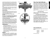
... free replacement. Service center locations are designed to page 4 for repair. FIG. 20 FIG. 20A RIGHT WRONG 13 Three Year Limited Warranty DEWALT will repair, without charge, any time during the cut these extrusions. This warranty gives you specific legal rights and you will accumulate. 3. ... but if need be, the saw blade before cutting. Repairs To assure product SAFETY and RELIABILITY, repairs, maintenance and adjustment (including brush inspection and replacement) should be easily cut . FREE WARNING LABEL REPLACEMENT: If your right thumb on page 7 or return the tool ...
... free replacement. Service center locations are designed to page 4 for repair. FIG. 20 FIG. 20A RIGHT WRONG 13 Three Year Limited Warranty DEWALT will repair, without charge, any time during the cut these extrusions. This warranty gives you specific legal rights and you will accumulate. 3. ... but if need be, the saw blade before cutting. Repairs To assure product SAFETY and RELIABILITY, repairs, maintenance and adjustment (including brush inspection and replacement) should be easily cut . FREE WARNING LABEL REPLACEMENT: If your right thumb on page 7 or return the tool ...
Instruction Manual
Page 16
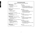
... Position bowed material as instructed on flat level surface. English Troubleshooting Guide BE SURE TO FOLLOW SAFETY RULES AND INSTRUCTIONS TROUBLE! Have brushes replaced by authorized service center. 4. Blade mounted backwards 3. See page 7. 4. Workpiece moving 4. Plug in 2. See page 5. ...WRONG? 1. Extension cord too light or too long 2. Reposition on page 7. Dull blade 2. MACHINE VIBRATES EXCESSIVELY WHAT'S WRONG? 1. Brushes worn out WHAT TO DO... 1. Replace fuse or reset circuit breaker. 3. TROUBLE! Check and adjust. See page 6. 2. Saw ...
... Position bowed material as instructed on flat level surface. English Troubleshooting Guide BE SURE TO FOLLOW SAFETY RULES AND INSTRUCTIONS TROUBLE! Have brushes replaced by authorized service center. 4. Blade mounted backwards 3. See page 7. 4. Workpiece moving 4. Plug in 2. See page 5. ...WRONG? 1. Extension cord too light or too long 2. Reposition on page 7. Dull blade 2. MACHINE VIBRATES EXCESSIVELY WHAT'S WRONG? 1. Brushes worn out WHAT TO DO... 1. Replace fuse or reset circuit breaker. 3. TROUBLE! Check and adjust. See page 6. 2. Saw ...

Instruction Manual - Laser
Page 8
Align the blade with the laser and prevent it from accurately indicating the line of cut . G NOTE: Repeat Steps 7-9 to edge of cut . • Follow miters saw's instruction manual to remove and install blade. • With blade removed from accurately indicating the line of framing square/blade. Pitch and debris can block the laser and prevent it from saw, clean pitch and build-up can interfere with the framing square. SPECIFICATIONS Light Source Semiconductor laser diode Laser Wavelength 630 - 680 nm Visible Laser Power Reattach the 2.5 mm hex wrench (D) in LPS. ...
Align the blade with the laser and prevent it from accurately indicating the line of cut . G NOTE: Repeat Steps 7-9 to edge of cut . • Follow miters saw's instruction manual to remove and install blade. • With blade removed from accurately indicating the line of framing square/blade. Pitch and debris can block the laser and prevent it from saw, clean pitch and build-up can interfere with the framing square. SPECIFICATIONS Light Source Semiconductor laser diode Laser Wavelength 630 - 680 nm Visible Laser Power Reattach the 2.5 mm hex wrench (D) in LPS. ...

Parts Diagram
Page 4
Page 2 Please visit www.dewaltservicenet.com for DW715 Type 1 Description Qty Required 330019-32 SCREW 6 145344-01 BOLT 1 151962-01 CLAMP,OUTER 1 152636-00 ADAPTOR,BLADE 1 141987-04 WASHER,INR CLMP 1 623017-00 ... CAP 1 330003-60 BEARING 1 330003-13 BEARING,BALL 1 144803-00 RING,RET. 1 146723-01 BAFFLE,FAN 1 145312-00 PLUG,RUBBER 1 448084-01 CAP,BRUSH 2 145323-06 BRUSH 2 147097-09 BRUSH HOLDER 2 COPYRIGHT© 2005. Item Number 28 29 30 31 32 34 35 36 37 38 42 43 45 46 48 49 50...
Page 2 Please visit www.dewaltservicenet.com for DW715 Type 1 Description Qty Required 330019-32 SCREW 6 145344-01 BOLT 1 151962-01 CLAMP,OUTER 1 152636-00 ADAPTOR,BLADE 1 141987-04 WASHER,INR CLMP 1 623017-00 ... CAP 1 330003-60 BEARING 1 330003-13 BEARING,BALL 1 144803-00 RING,RET. 1 146723-01 BAFFLE,FAN 1 145312-00 PLUG,RUBBER 1 448084-01 CAP,BRUSH 2 145323-06 BRUSH 2 147097-09 BRUSH HOLDER 2 COPYRIGHT© 2005. Item Number 28 29 30 31 32 34 35 36 37 38 42 43 45 46 48 49 50...

