
Instruction Manual
Page 3
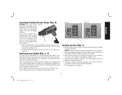
... insert screw strips when the screwdriver power is off and the trigger is earthed or grounded. • Disconnect the plug from the power source and/or the battery pack from the power tool before making any adjustments, changing accessories, or storing power tools. WARNING: To reduce the risk of starting the power tool accidentally • When driving screws, never reach into the magazine accessory. WARNING! Read all safety warnings and all instructions...
... insert screw strips when the screwdriver power is off and the trigger is earthed or grounded. • Disconnect the plug from the power source and/or the battery pack from the power tool before making any adjustments, changing accessories, or storing power tools. WARNING: To reduce the risk of starting the power tool accidentally • When driving screws, never reach into the magazine accessory. WARNING! Read all safety warnings and all instructions...
Instruction Manual
Page 4
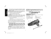
WARNING: Some dust created by power sanding, sawing, grinding, drilling, and other construction activities contains chemicals known to the State of California to ANSI S12.6 (S3.19) during use. Always use face or dust mask if cutting operation is dusty. Screw guide E. Release buttons D. Also use NIOSH/OSHA approved respiratory protection appropriate for the dust exposure. ALWAYS WEAR CERTIFIED SAFETY EQUIPMENT: • ANSI Z87.1 eye protection (CAN/CSA...
WARNING: Some dust created by power sanding, sawing, grinding, drilling, and other construction activities contains chemicals known to the State of California to ANSI S12.6 (S3.19) during use. Always use face or dust mask if cutting operation is dusty. Screw guide E. Release buttons D. Also use NIOSH/OSHA approved respiratory protection appropriate for the dust exposure. ALWAYS WEAR CERTIFIED SAFETY EQUIPMENT: • ANSI Z87.1 eye protection (CAN/CSA...
Instruction Manual
Page 5
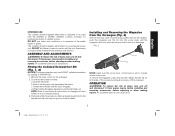
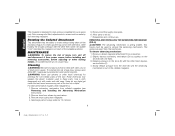
... injury, turn unit off and disconnect it from the screwgun. 2. d. Rotate the bit holder until ball lock snaps in your screwgun manual. 3. Supervision is set to and follow all instructions on both sides of collated screws. An accidental start -up can cause injury. 3 Page dimensions: 8.5 x 5.5 FIG. 2 H G NOTE: make sure the screw driver control lever is required when inexperienced operators use DEWALT collated screwdriver bit (catalog #: DWA6PHC2). 1. ASSEMBLY AND ADJUSTMENTS WARNING...
... injury, turn unit off and disconnect it from the screwgun. 2. d. Rotate the bit holder until ball lock snaps in your screwgun manual. 3. Supervision is set to and follow all instructions on both sides of collated screws. An accidental start -up can cause injury. 3 Page dimensions: 8.5 x 5.5 FIG. 2 H G NOTE: make sure the screw driver control lever is required when inexperienced operators use DEWALT collated screwdriver bit (catalog #: DWA6PHC2). 1. ASSEMBLY AND ADJUSTMENTS WARNING...
Instruction Manual
Page 6
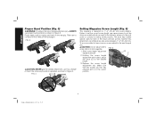
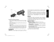
... specific slots for 1"- 2" (20- 50 mm) screw lengths. Proper hand position requires one hand on the screwgun. To accommodate for less common screws adjust to not block the air vents on the rear grip. FIG. 4 Setting Magazine Screw Length (Fig. 5) This magazine is designed for each of serious personal injury, ALWAYS use it as a handle or touch the screw strips while in operation...
... specific slots for 1"- 2" (20- 50 mm) screw lengths. Proper hand position requires one hand on the screwgun. To accommodate for less common screws adjust to not block the air vents on the rear grip. FIG. 4 Setting Magazine Screw Length (Fig. 5) This magazine is designed for each of serious personal injury, ALWAYS use it as a handle or touch the screw strips while in operation...
Instruction Manual
Page 7
... advancing mechanism (D). 2. Turn the fine depth adjustment (C) clockwise to reduce the screw drive depth into alignment with screwdriver bit. 6. Before driving screws, ensure screwgun drive direction is a gauge next to forward position. Apply pressure against work piece. 3. Proper use new, undamaged strips D A free of collated strips will advance screw into the work piece. For best performance use of debris. 1. There is switched to the adjustment wheel which displays the screw depth setting. With the magazine installed on the screwgun...
... advancing mechanism (D). 2. Turn the fine depth adjustment (C) clockwise to reduce the screw drive depth into alignment with screwdriver bit. 6. Before driving screws, ensure screwgun drive direction is a gauge next to forward position. Apply pressure against work piece. 3. Proper use new, undamaged strips D A free of collated strips will advance screw into the work piece. For best performance use of debris. 1. There is switched to the adjustment wheel which displays the screw depth setting. With the magazine installed on the screwgun...
Instruction Manual
Page 8
..., dry air at least once a week. Use a cloth dampened only with one hand, while holding the drywall screwgun with the other hand depress service button (F). 4. never immerse any liquid get inside the tool; Allow parts to screw must be made by : 1. REMOVING AND INSTALLING THE ADVANCING MECHANISM (FIG. 8) CAUTION: The advancing mechanism is designed to drive screws completely into a liquid. The spring may weaken...
..., dry air at least once a week. Use a cloth dampened only with one hand, while holding the drywall screwgun with the other hand depress service button (F). 4. never immerse any liquid get inside the tool; Allow parts to screw must be made by : 1. REMOVING AND INSTALLING THE ADVANCING MECHANISM (FIG. 8) CAUTION: The advancing mechanism is designed to drive screws completely into a liquid. The spring may weaken...
Instruction Manual
Page 9
... service button. Recommended accessories for use identical replacement parts. Register your product now for: • WARRANTY SERVICE: Registering your product will allow us to ensure proper function before the advancing mechanism is required under the Federal Consumer Safety Act. Always use . Repairs To assure product SAFETY and RELIABILITY, repairs, maintenance and adjustment (including brush inspection and replacement) should be locked in the unlikely event a safety notification is installed. dewalt.com. Register online...
... service button. Recommended accessories for use identical replacement parts. Register your product now for: • WARRANTY SERVICE: Registering your product will allow us to ensure proper function before the advancing mechanism is required under the Federal Consumer Safety Act. Always use . Repairs To assure product SAFETY and RELIABILITY, repairs, maintenance and adjustment (including brush inspection and replacement) should be locked in the unlikely event a safety notification is installed. dewalt.com. Register online...

Instruction Manual
Page 10
... warranty, DEWALT tools are covered by our: 1 YEAR FREE SERVICE DEWALT will repair, without charge, any reason, you may have been made or attempted by others. FREE WARNING LABEL REPLACEMENT: If your DEWALT Power Tool, Laser, or Nailer for any defects due to products sold in Latin America, see country specific warranty information contained in certain states or provinces. This warranty does not cover part failure due to accessories...
... warranty, DEWALT tools are covered by our: 1 YEAR FREE SERVICE DEWALT will repair, without charge, any reason, you may have been made or attempted by others. FREE WARNING LABEL REPLACEMENT: If your DEWALT Power Tool, Laser, or Nailer for any defects due to products sold in Latin America, see country specific warranty information contained in certain states or provinces. This warranty does not cover part failure due to accessories...

Instruction Manual
Page 32
Page dimensions: 8.5 x 5.5 and the array of lozenge-shaped humps on the surface of pyramids on the handgrip; the kit box configuration; the array of the tool. N426966 DCF6201 Copyright © 2015 DEWALT The following are trademarks for one or more DEWALT power tools: the yellow and black color scheme; DEWALT Industrial Tool Co., 701 East Joppa Road, Towson, MD 21286 (JAN15) Part No. the "D" shaped air intake grill;
Page dimensions: 8.5 x 5.5 and the array of lozenge-shaped humps on the surface of pyramids on the handgrip; the kit box configuration; the array of the tool. N426966 DCF6201 Copyright © 2015 DEWALT The following are trademarks for one or more DEWALT power tools: the yellow and black color scheme; DEWALT Industrial Tool Co., 701 East Joppa Road, Towson, MD 21286 (JAN15) Part No. the "D" shaped air intake grill;


