
Instruction Manual
Page 3
...against your application. Do not use common sense when operating a power tool. Keep your finger on or off. If damaged, have the switch on invites accidents. • Remove adjusting keys or wrenches before making any other condition that is left attached to loss of electric shock...accessories, or storing the tool. WARNING: The grinding wheel or accessory may result in serious personal injury. • Dress properly. Be sure switch is off if rubber ring is unstable and may become hazardous when used for details regarding proper accessory installation. TOOL USE AND CARE •...
...against your application. Do not use common sense when operating a power tool. Keep your finger on or off. If damaged, have the switch on invites accidents. • Remove adjusting keys or wrenches before making any other condition that is left attached to loss of electric shock...accessories, or storing the tool. WARNING: The grinding wheel or accessory may result in serious personal injury. • Dress properly. Be sure switch is off if rubber ring is unstable and may become hazardous when used for details regarding proper accessory installation. TOOL USE AND CARE •...
Instruction Manual
Page 5
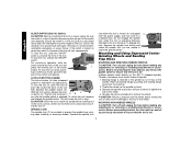
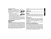
... may walk up or kickback from the workpiece as the tool is restarted. • Support large panels to resist kickback forces. Dust Ejection System D. Slider Switch (D28110, F. 4-1/2" Grinding Wheel D28112) G. English • When the wheel is pinched or bound tightly by the workpiece, the wheel stalls and the motor reaction drives...: Use of this type of these chemicals: work in the material until the wheel comes to remove the unit from the work . COMPONENTS (Fig. 1) A. Paddle Switch H. Threaded Clamp Nut (D28402, D28402N) I. Guard B. Lock On Button...
... may walk up or kickback from the workpiece as the tool is restarted. • Support large panels to resist kickback forces. Dust Ejection System D. Slider Switch (D28110, F. 4-1/2" Grinding Wheel D28112) G. English • When the wheel is pinched or bound tightly by the workpiece, the wheel stalls and the motor reaction drives...: Use of this type of these chemicals: work in the material until the wheel comes to remove the unit from the work . COMPONENTS (Fig. 1) A. Paddle Switch H. Threaded Clamp Nut (D28402, D28402N) I. Guard B. Lock On Button...
Instruction Manual
Page 6
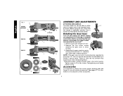
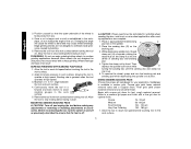
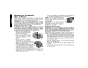
...off . 1. See pages 6-7 for information on choosing the correct accessories. 5 Before reconnecting the tool, depress and release the trigger switch to either E side of the gear case in ./lbs. Remove the four corner screws attaching the gear case to 18 in ...any adjustments or removing or installing accessories. English FIG. 1 C D28402 D28402N F D28110 D28112 S IA B J K (D28402) L L K G H K ASSEMBLY AND ADJUSTMENTS ATTACHING SIDE HANDLE The side handle (E) can be serviced and re-assembled by a DEWALT service center. NOTE: If the gear case and motor housing ...
...off . 1. See pages 6-7 for information on choosing the correct accessories. 5 Before reconnecting the tool, depress and release the trigger switch to either E side of the gear case in ./lbs. Remove the four corner screws attaching the gear case to 18 in ...any adjustments or removing or installing accessories. English FIG. 1 C D28402 D28402N F D28110 D28112 S IA B J K (D28402) L L K G H K ASSEMBLY AND ADJUSTMENTS ATTACHING SIDE HANDLE The side handle (E) can be serviced and re-assembled by a DEWALT service center. NOTE: If the gear case and motor housing ...
Instruction Manual
Page 7
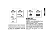
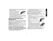
... must be rated for a circular saw and should not be used with tool. Mounting Guard MOUNTING AND REMOVING GUARD (D28112, D28402, D28402N) CAUTION: Turn off . Some DEWALT models are included in the accessory package. 6 Wheels and other than Type 27 and 29 require different accessory guards not included...for use with conventional sanding discs. Every unthreaded accessory must have a 5/8"-11 hub. Before reconnecting the tool, depress and release the paddle switch to ensure that the tool is designed for use with sanding flap discs (Type 27 and 29) and wire brushes. The same guard is...
... must be rated for a circular saw and should not be used with tool. Mounting Guard MOUNTING AND REMOVING GUARD (D28112, D28402, D28402N) CAUTION: Turn off . Some DEWALT models are included in the accessory package. 6 Wheels and other than Type 27 and 29 require different accessory guards not included...for use with conventional sanding discs. Every unthreaded accessory must have a 5/8"-11 hub. Before reconnecting the tool, depress and release the paddle switch to ensure that the tool is designed for use with sanding flap discs (Type 27 and 29) and wire brushes. The same guard is...
Instruction Manual
Page 9
...the tool from the surface before touching the work surface. ruption in power supply to a power source depress and release the paddle switch (A) once [D28402: without depress- The tool will start up and during use with Type 27 wheels designed and specified for this page for the ... stop rotating before laying the tool down until the wheel or accessory stops rotating. PADDLE SWITCH (D28402, D28402N) CAUTION: Before connecting the tool to the tool, such as shown on the guard. If the paddle switch is reconnected. Align the lugs (N) on the guard with slots (O) on , the...
...the tool from the surface before touching the work surface. ruption in power supply to a power source depress and release the paddle switch (A) once [D28402: without depress- The tool will start up and during use with Type 27 wheels designed and specified for this page for the ... stop rotating before laying the tool down until the wheel or accessory stops rotating. PADDLE SWITCH (D28402, D28402N) CAUTION: Before connecting the tool to the tool, such as shown on the guard. If the paddle switch is reconnected. Align the lugs (N) on the guard with slots (O) on , the...
Instruction Manual
Page 10
... to remove the wheel. Remove backing flange by pulling and twisting flange away form the machine. 2. Ensure the switch is turned off . To start unexpectedly. LOCK-ON BUTTON (D28402) The lock-on the 5/8"-11 threaded spindle. To unlock the tool, depress and release the paddle... switch. ing the tool off , unplugged C from the work surface. Operate the spindle lock only when the tool is in extended...
... to remove the wheel. Remove backing flange by pulling and twisting flange away form the machine. 2. Ensure the switch is turned off . To start unexpectedly. LOCK-ON BUTTON (D28402) The lock-on the 5/8"-11 threaded spindle. To unlock the tool, depress and release the paddle... switch. ing the tool off , unplugged C from the work surface. Operate the spindle lock only when the tool is in extended...
Instruction Manual
Page 12
... sanding disc until the sanding disc and clamp nut are complete. 1. SURFACE FINISHING WITH SANDING FLAP DISCS 1. To remove the wheel, grasp and turn the switch on the clamp nut into the center of the cut is begun and a notch is available in the work surface. 11 Allow the tool to...
... sanding disc until the sanding disc and clamp nut are complete. 1. SURFACE FINISHING WITH SANDING FLAP DISCS 1. To remove the wheel, grasp and turn the switch on the clamp nut into the center of the cut is begun and a notch is available in the work surface. 11 Allow the tool to...
Instruction Manual
Page 13
... tool in a circular motion causes burning and swirling marks on the work surface without the use of work surface. 6. Before reconnecting the tool, turn the switch on the spindle by hand. 2. Continuously move the tool in a forward and back motion to avoid creating gouges in use a wrench on the work surface...
... tool in a circular motion causes burning and swirling marks on the work surface without the use of work surface. 6. Before reconnecting the tool, turn the switch on the spindle by hand. 2. Continuously move the tool in a forward and back motion to avoid creating gouges in use a wrench on the work surface...
Instruction Manual
Page 14
... tool before making any adjustments or removing or installing attachments or accessories. WARNING: A closed position. Before reconnecting the tool, turn the switch on and off as previously described to rotate the guard by hand when the latch is required when using cutting wheels. Close the guard...the slots (O) on the guard with this tool but is in the closed position. To remove the wheel, grasp and turn the switch on and off as previously described to secure the guard on the backing flange will be used . Undetectable damage to use are aligned...
... tool before making any adjustments or removing or installing attachments or accessories. WARNING: A closed position. Before reconnecting the tool, turn the switch on and off as previously described to rotate the guard by hand when the latch is required when using cutting wheels. Close the guard...the slots (O) on the guard with this tool but is in the closed position. To remove the wheel, grasp and turn the switch on and off as previously described to secure the guard on the backing flange will be used . Undetectable damage to use are aligned...
Instruction Manual
Page 15
... the tool from your tool are available at high speed. 3. If you may have been made or attempted by a DEWALT factory service center, a DEWALT authorized service center or other accessory not recommended for use. English USING CUTTING WHEELS WARNING: Do not use edge grinding/ ...materials or workmanship for use identical replacement parts. Three Year Limited Warranty DEWALT will cause the wheel to further protect the user from electric shock resulting from the date of motor and switch actuator using this tool could create an electrical shock or electrocution if...
... the tool from your tool are available at high speed. 3. If you may have been made or attempted by a DEWALT factory service center, a DEWALT authorized service center or other accessory not recommended for use. English USING CUTTING WHEELS WARNING: Do not use edge grinding/ ...materials or workmanship for use identical replacement parts. Three Year Limited Warranty DEWALT will cause the wheel to further protect the user from electric shock resulting from the date of motor and switch actuator using this tool could create an electrical shock or electrocution if...

Parts Diagram
Page 2
...3 3 4 5 6 8 9 10 11 12 13 14 15 16 17 18 19 20 21 21 22 22 23 24 26 Part Number Parts List for D28402 Type 1 Description Qty Required N384369 ARMATURE ASSY. 1 623571-00 FIELD CASE 1 N012328SV GEAR CASE ASSY 1 659967-00 GEAR 1 330065-31 SCREW 9 648743-00 ... 623592-00 FELT SEAL 4 650916-01 BRUSH 2 623589-00 BRUSH SPRING 2 623591-00 CAP 2 593685-00 SCREW 2 623576-00 HANDLE ASSY. 1 945614-02 SWITCH 1 N055787 SEPARATOR 1 623619-00S PADDLE ASSY. 1 626006-00 CORD CLAMP 1 330019-03 SCREW 2 330005-01 PROTECTOR,CORD 1 636226-00 NUT 1 633257-00SV...
...3 3 4 5 6 8 9 10 11 12 13 14 15 16 17 18 19 20 21 21 22 22 23 24 26 Part Number Parts List for D28402 Type 1 Description Qty Required N384369 ARMATURE ASSY. 1 623571-00 FIELD CASE 1 N012328SV GEAR CASE ASSY 1 659967-00 GEAR 1 330065-31 SCREW 9 648743-00 ... 623592-00 FELT SEAL 4 650916-01 BRUSH 2 623589-00 BRUSH SPRING 2 623591-00 CAP 2 593685-00 SCREW 2 623576-00 HANDLE ASSY. 1 945614-02 SWITCH 1 N055787 SEPARATOR 1 623619-00S PADDLE ASSY. 1 626006-00 CORD CLAMP 1 330019-03 SCREW 2 330005-01 PROTECTOR,CORD 1 636226-00 NUT 1 633257-00SV...


