
Instruction Manual
Page 4
...Ejection System (DES) away from operator and coworkers. Never start fires. • Always use . The side handle should burst in this tool. A guard protects operator from broken wheel fragments and wheel contact. • Accessories must be above listed minimum wheel speed as follows: V ..........volts A amperes ...hazardous. Sparks may cause burns or start the tool with a "live " and shock the operator. • Do not use proper guard with the wheel. If the wire brush has loose wires, they will make exposed metal parts of accessories not specified in less than...
...Ejection System (DES) away from operator and coworkers. Never start fires. • Always use . The side handle should burst in this tool. A guard protects operator from broken wheel fragments and wheel contact. • Accessories must be above listed minimum wheel speed as follows: V ..........volts A amperes ...hazardous. Sparks may cause burns or start the tool with a "live " and shock the operator. • Do not use proper guard with the wheel. If the wire brush has loose wires, they will make exposed metal parts of accessories not specified in less than...
Instruction Manual
Page 5
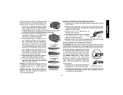
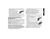
... approved respiratory protection appropriate for any reason, release the trigger and hold the unit motionless in the material until the wheel comes to hearing loss. Guard B. Lock-Off Lever J. Spindle (not shown) (DES) E. WARNING: Some dust created by power sanding, sawing, grinding, drilling, and other ...cause of wheel binding. • When restarting a cut-off tool in motion or kickback may occur. Lock On Button (D28402) C. Anti-Lockup Backing Flange 4 Spindle Lock Button K. Allowing dust to minimize the risk of wheel pinching and kickback. Threaded Clamp Nut...
... approved respiratory protection appropriate for any reason, release the trigger and hold the unit motionless in the material until the wheel comes to hearing loss. Guard B. Lock-Off Lever J. Spindle (not shown) (DES) E. WARNING: Some dust created by power sanding, sawing, grinding, drilling, and other ...cause of wheel binding. • When restarting a cut-off tool in motion or kickback may occur. Lock On Button (D28402) C. Anti-Lockup Backing Flange 4 Spindle Lock Button K. Allowing dust to minimize the risk of wheel pinching and kickback. Threaded Clamp Nut...
Instruction Manual
Page 6
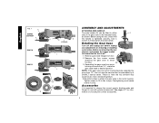
... brush, motor and bearing failure. 3. Accessories It is important to choose the correct guards, backing pads and flanges to desired position. Rotating the Gear Case Turn off . ... from tool. 2. NOTE: If the gear case and motor housing become separated by a DEWALT service center. Use a wrench to motor housing. 90˚ 90˚ 3. Remove the.... See pages 6-7 for information on choosing the correct accessories. 5 English FIG. 1 C D28402 D28402N F D28110 D28112 S IA B J K (D28402) L L K G H K ASSEMBLY AND ADJUSTMENTS ATTACHING SIDE HANDLE The side handle (E) ...
... brush, motor and bearing failure. 3. Accessories It is important to choose the correct guards, backing pads and flanges to desired position. Rotating the Gear Case Turn off . ... from tool. 2. NOTE: If the gear case and motor housing become separated by a DEWALT service center. Use a wrench to motor housing. 90˚ 90˚ 3. Remove the.... See pages 6-7 for information on choosing the correct accessories. 5 English FIG. 1 C D28402 D28402N F D28110 D28112 S IA B J K (D28402) L L K G H K ASSEMBLY AND ADJUSTMENTS ATTACHING SIDE HANDLE The side handle (E) ...
Instruction Manual
Page 7
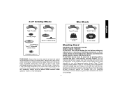
... release the paddle switch to ensure that the tool is designed for use with conventional sanding discs. Some DEWALT models are included in the accessory package. 6 CAUTION: Guards must be used. Grinding and cutting with sanding flap discs (Type 27 and 29) and wire brushes.... for at least the speed recommended on pages 6-7 of this manual. Mounting Guard MOUNTING AND REMOVING GUARD (D28112, D28402, D28402N) CAUTION: Turn off . Wheels and other than Type 27 and 29 require different accessory guards not included with all grinding wheels, sanding flap discs, wire brushes, and ...
... release the paddle switch to ensure that the tool is designed for use with conventional sanding discs. Some DEWALT models are included in the accessory package. 6 CAUTION: Guards must be used. Grinding and cutting with sanding flap discs (Type 27 and 29) and wire brushes.... for at least the speed recommended on pages 6-7 of this manual. Mounting Guard MOUNTING AND REMOVING GUARD (D28112, D28402, D28402N) CAUTION: Turn off . Wheels and other than Type 27 and 29 require different accessory guards not included with all grinding wheels, sanding flap discs, wire brushes, and ...
Instruction Manual
Page 8
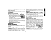
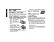
...cutting wheel diamond cutting wheel clamp nut clamp nut 1. Align N the lugs (N) on the guard with the slots (O) on the gear O case hub. Push the guard down until the guard lugs engage and rotate freely in the groove on the gear case. 2. Do not operate the... grinder with clamp lever in open position. 5. NOTE: The guard is closed position. To remove the guard, open , rotate the guard (I 7 M 3. I ) into the desired working po sition. Close the guard latch to secure the guard on the guard. If, after a period of the gear case hub at the factory...
...cutting wheel diamond cutting wheel clamp nut clamp nut 1. Align N the lugs (N) on the guard with the slots (O) on the gear O case hub. Push the guard down until the guard lugs engage and rotate freely in the groove on the gear case. 2. Do not operate the... grinder with clamp lever in open position. 5. NOTE: The guard is closed position. To remove the guard, open , rotate the guard (I 7 M 3. I ) into the desired working po sition. Close the guard latch to secure the guard on the guard. If, after a period of the gear case hub at the factory...
Instruction Manual
Page 9
...27 wheels designed and specified for this page for the correct accessories. Make sure the wheel has come to rotate the guard by hand. PADDLE SWITCH (D28402, D28402N) CAUTION: Before connecting the tool to stop before putting it is laid down . Depress and release the ...then depress the paddle switch (A). Allow the tool to a power source depress and release the paddle switch (A) once [D28402: without depress- If the lock-off . MOUNTING AND REMOVING GUARD (D28110) O N 1. Accessory ratings must have been designed for at start up and during use with the grinder ...
...27 wheels designed and specified for this page for the correct accessories. Make sure the wheel has come to rotate the guard by hand. PADDLE SWITCH (D28402, D28402N) CAUTION: Before connecting the tool to stop before putting it is laid down . Depress and release the ...then depress the paddle switch (A). Allow the tool to a power source depress and release the paddle switch (A) once [D28402: without depress- If the lock-off . MOUNTING AND REMOVING GUARD (D28110) O N 1. Accessory ratings must have been designed for at start up and during use with the grinder ...
Instruction Manual
Page 11
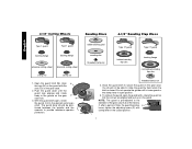
...the tool is tightened, check the orientation of the backing flange. 3. ton, thread the clamp nut (H) on spindle (D) with a standard Type 27 guard to operate at high speed. If the wheel you are installing is 1/8" (3.31mm) thick or less, place the threaded clamp nut on the raised sec...before touching the tool to the work surface, allowing the tool to shallow cutting and notching (less than 1/2" in the work surface. 4. Type 1 guards are installing is seated onto the flats of this manual for more than 1/8" (3.31mm) thick, place the threaded clamp nut on the spindle so ...
...the tool is tightened, check the orientation of the backing flange. 3. ton, thread the clamp nut (H) on spindle (D) with a standard Type 27 guard to operate at high speed. If the wheel you are installing is 1/8" (3.31mm) thick or less, place the threaded clamp nut on the raised sec...before touching the tool to the work surface, allowing the tool to shallow cutting and notching (less than 1/2" in the work surface. 4. Type 1 guards are installing is seated onto the flats of this manual for more than 1/8" (3.31mm) thick, place the threaded clamp nut on the spindle so ...
Instruction Manual
Page 12
... work surface before laying it down . Before reconnecting the tool, turn the backing pad and sanding pad while depressing the spindle lock button. CAUTION: Proper guard must be reinstalled for surface grinding applications because these wheels are snug. 5. While depressing spindle lock, thread clamp nut (H) on spindle, piloting the raised hub...
... work surface before laying it down . Before reconnecting the tool, turn the backing pad and sanding pad while depressing the spindle lock button. CAUTION: Proper guard must be reinstalled for surface grinding applications because these wheels are snug. 5. While depressing spindle lock, thread clamp nut (H) on spindle, piloting the raised hub...
Instruction Manual
Page 13
...work surface before turning tool off and unplug the tool before turning the tool off . 1. Remove the tool from work surface. 6. A Type 27 guard is greatest when the tool operates at high speed. 3. They can be experienced. 12 Allowing the tool to operate at high speed. Allow the ... tool in a forward and back motion to avoid creating gouges in damage to tighten the wheel. 3. CAUTION: Wheel or brush must not touch guard when mounted or while in a straight 5˚-15˚ line to reach full speed before turning the tool on the work surface. Allow the...
...work surface before turning tool off and unplug the tool before turning the tool off . 1. Remove the tool from work surface. 6. A Type 27 guard is greatest when the tool operates at high speed. 3. They can be experienced. 12 Allowing the tool to operate at high speed. Allow the ... tool in a forward and back motion to avoid creating gouges in damage to tighten the wheel. 3. CAUTION: Wheel or brush must not touch guard when mounted or while in a straight 5˚-15˚ line to reach full speed before turning the tool on the work surface. Allow the...
Instruction Manual
Page 14
... with a wrench. 5. Before reconnecting the tool, turn while depressing the spindle lock button. 13 Place the unthreaded backing flange on the guard. Place the wheel on the backing flange, centering the wheel on the gear case cover. Install the threaded clamp nut with the raised ...or removing or installing attachments or accessories. The raised section (pilot) on the gear case. 2. Open the guard latch (M). If rotation is off . Failure to secure the guard on the raised section (pilot). 3. See page 7 for concrete cutting can result in the closed position. ...
... with a wrench. 5. Before reconnecting the tool, turn while depressing the spindle lock button. 13 Place the unthreaded backing flange on the guard. Place the wheel on the backing flange, centering the wheel on the gear case cover. Install the threaded clamp nut with the raised ...or removing or installing attachments or accessories. The raised section (pilot) on the gear case. 2. Open the guard latch (M). If rotation is off . Failure to secure the guard on the raised section (pilot). 3. See page 7 for concrete cutting can result in the closed position. ...

Parts Diagram
Page 2
...2 3 3 4 5 6 8 9 10 11 12 13 14 15 16 17 18 19 20 21 21 22 22 23 24 26 Part Number Parts List for D28402 Type 1 Description Qty Required N384369 ARMATURE ASSY. 1 623571-00 FIELD CASE 1 N012328SV GEAR CASE ASSY 1 659967-00 GEAR 1 330065-31 SCREW 9 648743-00 ARM 2...-00S PADDLE ASSY. 1 626006-00 CORD CLAMP 1 330019-03 SCREW 2 330005-01 PROTECTOR,CORD 1 636226-00 NUT 1 633257-00SV BACKING FLANGE 1 N342329 GUARD 1 397661-01 GUARD 1 625415-00 PLUG 1 625323-00 LOCK-ON BUTTON 1 562210-00 SPRING 1 330072-98 CORD/8FT/18-2SJ 1 623593-00 TERMINAL 2
...2 3 3 4 5 6 8 9 10 11 12 13 14 15 16 17 18 19 20 21 21 22 22 23 24 26 Part Number Parts List for D28402 Type 1 Description Qty Required N384369 ARMATURE ASSY. 1 623571-00 FIELD CASE 1 N012328SV GEAR CASE ASSY 1 659967-00 GEAR 1 330065-31 SCREW 9 648743-00 ARM 2...-00S PADDLE ASSY. 1 626006-00 CORD CLAMP 1 330019-03 SCREW 2 330005-01 PROTECTOR,CORD 1 636226-00 NUT 1 633257-00SV BACKING FLANGE 1 N342329 GUARD 1 397661-01 GUARD 1 625415-00 PLUG 1 625323-00 LOCK-ON BUTTON 1 562210-00 SPRING 1 330072-98 CORD/8FT/18-2SJ 1 623593-00 TERMINAL 2

Parts Diagram
Page 4
Item Number 800 800 836 846 846 856 856 856 861 Part Number 429954-00 429954-01 233804-36 5140030-98 625415-00 N342331 643772-00 DW4514 651196-00 Parts List for D28402 Type 1 Description Qty Required GREASE, 7LBS 1 GREASE,1 LB. 1 TORX DRIVER 1 SHIM 1 PLUG 1 GUARD 1 GUARD 1 4-1/2X1/4 METL 1 KITBOX 1 DEWALT ELECTRIC POWER TOOLS
Item Number 800 800 836 846 846 856 856 856 861 Part Number 429954-00 429954-01 233804-36 5140030-98 625415-00 N342331 643772-00 DW4514 651196-00 Parts List for D28402 Type 1 Description Qty Required GREASE, 7LBS 1 GREASE,1 LB. 1 TORX DRIVER 1 SHIM 1 PLUG 1 GUARD 1 GUARD 1 4-1/2X1/4 METL 1 KITBOX 1 DEWALT ELECTRIC POWER TOOLS