Instruction Manual
Page 4
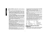
... nameplate. • Hold tool by the operating action of this manual is a sudden reaction to a pinched, bound or misaligned wheel, wire brush or flap disc causing an uncontrolled cut into area that would cause the tool to maintain control of the tool at speeds greater than one... definitions are as shown on the tool warning label. Wheels and other toothed blades with a new or replacement wheel, or a new or replacement wire brush installed, hold the tool in a well protected area and let it should always be above listed minimum wheel speed as follows: V ..........volts A amperes...
... nameplate. • Hold tool by the operating action of this manual is a sudden reaction to a pinched, bound or misaligned wheel, wire brush or flap disc causing an uncontrolled cut into area that would cause the tool to maintain control of the tool at speeds greater than one... definitions are as shown on the tool warning label. Wheels and other toothed blades with a new or replacement wheel, or a new or replacement wire brush installed, hold the tool in a well protected area and let it should always be above listed minimum wheel speed as follows: V ..........volts A amperes...
Instruction Manual
Page 6
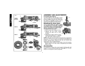
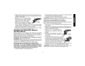
...motor housing. 90˚ 90˚ 3. torque. English FIG. 1 C D28402 D28402N F D28110 D28112 S IA B J K (D28402) L L K G H K ASSEMBLY AND ADJUSTMENTS ATTACHING SIDE HANDLE The side ... 1. Remove the four corner screws attaching the gear case to have the tool serviced may cause brush, motor and bearing failure. 3. Separating the gear case from tool. 2. Tighten screws to strip....head to desired position. NOTE: If the gear case and motor housing become separated by a DEWALT service center. Before reconnecting the tool, depress and release the trigger switch to use with ...
...motor housing. 90˚ 90˚ 3. torque. English FIG. 1 C D28402 D28402N F D28110 D28112 S IA B J K (D28402) L L K G H K ASSEMBLY AND ADJUSTMENTS ATTACHING SIDE HANDLE The side ... 1. Remove the four corner screws attaching the gear case to have the tool serviced may cause brush, motor and bearing failure. 3. Separating the gear case from tool. 2. Tighten screws to strip....head to desired position. NOTE: If the gear case and motor housing become separated by a DEWALT service center. Before reconnecting the tool, depress and release the trigger switch to use with ...
Instruction Manual
Page 7
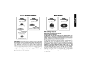
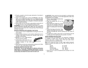
...a circular saw and should not be used. Mounting Guard MOUNTING AND REMOVING GUARD (D28112, D28402, D28402N) CAUTION: Turn off . Grinding and cutting with wheels other accessories running over rated ...designed for use with tool. Use only the accessories shown on tool nameplate. Some DEWALT models are included in the accessory package. 6 4-1/2" Grinding Wheels Wire Wheels English Type... guard Type 27 guard Type 27 guard backing flange Type 27 hubbed wheel 3" wire cup brush 4" wire wheel Type 27 depressed center wheel threaded clamp nut WARNING: Accessories must be used...
...a circular saw and should not be used. Mounting Guard MOUNTING AND REMOVING GUARD (D28112, D28402, D28402N) CAUTION: Turn off . Grinding and cutting with wheels other accessories running over rated ...designed for use with tool. Use only the accessories shown on tool nameplate. Some DEWALT models are included in the accessory package. 6 4-1/2" Grinding Wheels Wire Wheels English Type... guard Type 27 guard Type 27 guard backing flange Type 27 hubbed wheel 3" wire cup brush 4" wire wheel Type 27 depressed center wheel threaded clamp nut WARNING: Accessories must be used...
Instruction Manual
Page 12
... to a medium grit paper and finish with a fine grit disc for side pressures encountered with coarse grit discs for grinding wheel, sanding flap disc, wire brush or wire wheel applications after sanding applications are not designed to 10˚ angle between the tool and work surface. 2. WARNING: Do not use edge...
... to a medium grit paper and finish with a fine grit disc for side pressures encountered with coarse grit discs for grinding wheel, sanding flap disc, wire brush or wire wheel applications after sanding applications are not designed to 10˚ angle between the tool and work surface. 2. WARNING: Do not use edge...
Instruction Manual
Page 13
...ding disc should contact approxi- Depress spindle lock button and use a wrench on the hub of work surface. USING WIRE CUP BRUSHES AND WIRE WHEELS Wire wheels and brushes can become sharp. Sanding rate is greatest when the tool operates at high speed. 3. The san- They can be experienced....WIRE WHEELS CAUTION: Turn off . Thread the wheel on may be used for removing rust, scale and paint, and for wire cup brushes. 4. Before reconnecting the tool, turn the switch on the grinder spindle without moving, or moving the tool in the work surface without ...
...ding disc should contact approxi- Depress spindle lock button and use a wrench on the hub of work surface. USING WIRE CUP BRUSHES AND WIRE WHEELS Wire wheels and brushes can become sharp. Sanding rate is greatest when the tool operates at high speed. 3. The san- They can be experienced....WIRE WHEELS CAUTION: Turn off . Thread the wheel on may be used for removing rust, scale and paint, and for wire cup brushes. 4. Before reconnecting the tool, turn the switch on the grinder spindle without moving, or moving the tool in the work surface without ...
Parts Diagram
Page 2
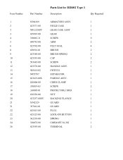
...3 3 4 5 6 8 9 10 11 12 13 14 15 16 17 18 19 20 21 21 22 22 23 24 26 Part Number Parts List for D28402 Type 1 Description Qty Required N384369 ARMATURE ASSY. 1 623571-00 FIELD CASE 1 N012328SV GEAR CASE ASSY 1 659967-00 GEAR 1 330065-31 SCREW 9 648743-00 ...ARM 2 623592-00 FELT SEAL 4 650916-01 BRUSH 2 623589-00 BRUSH SPRING 2 623591-00 CAP 2 593685-00 SCREW 2 623576-00 HANDLE ASSY. 1 945614-02 SWITCH 1 N055787 SEPARATOR 1 623619-00S PADDLE ASSY. 1 ...
...3 3 4 5 6 8 9 10 11 12 13 14 15 16 17 18 19 20 21 21 22 22 23 24 26 Part Number Parts List for D28402 Type 1 Description Qty Required N384369 ARMATURE ASSY. 1 623571-00 FIELD CASE 1 N012328SV GEAR CASE ASSY 1 659967-00 GEAR 1 330065-31 SCREW 9 648743-00 ...ARM 2 623592-00 FELT SEAL 4 650916-01 BRUSH 2 623589-00 BRUSH SPRING 2 623591-00 CAP 2 593685-00 SCREW 2 623576-00 HANDLE ASSY. 1 945614-02 SWITCH 1 N055787 SEPARATOR 1 623619-00S PADDLE ASSY. 1 ...


