Instruction Manual
Page 4
... operator. • Do not use proper guard with the wheel. Never start fires. • Always use . Sparks may cause serious personal injury. • Always use Type 11 (flaring cup) wheels on the tool warning label. Using inappropriate accessories can fly apart and cause injury. Use of time. Sparks may dismount from...
... operator. • Do not use proper guard with the wheel. Never start fires. • Always use . Sparks may cause serious personal injury. • Always use Type 11 (flaring cup) wheels on the tool warning label. Using inappropriate accessories can fly apart and cause injury. Use of time. Sparks may dismount from...
Instruction Manual
Page 5
... working into a corner because a sudden, sharp movement of the grinder may occur. COMPONENTS (Fig. 1) A. Threaded Clamp Nut (D28402, D28402N) I. Lock On Button (D28402) C. Never attempt to remove the unit from these exposures varies, depending on how often you to resist kickback forces. Investigate and ... respiratory or other accessory contacts a secondary surface or a surface edge. Under some conditions and duration of use, noise from this type of work in the material until the wheel comes to allow you do this product may promote absorption of these chemicals: work ....
... working into a corner because a sudden, sharp movement of the grinder may occur. COMPONENTS (Fig. 1) A. Threaded Clamp Nut (D28402, D28402N) I. Lock On Button (D28402) C. Never attempt to remove the unit from these exposures varies, depending on how often you to resist kickback forces. Investigate and ... respiratory or other accessory contacts a secondary surface or a surface edge. Under some conditions and duration of use, noise from this type of work in the material until the wheel comes to allow you do this product may promote absorption of these chemicals: work ....
Instruction Manual
Page 7
Mounting Guard MOUNTING AND REMOVING GUARD (D28112, D28402, D28402N) CAUTION: Turn off . If it does not, it may have been designed for a circular saw and should not be used with all grinding wheels, ... speed recommended on the tool warning label. Wheels and other than Type 27 and 29 require different accessory guards not included with conventional sanding discs. CAUTION: Guards must be used . Use only the accessories shown on pages 6-7 of this manual. Some DEWALT models are included in the accessory package. 6 The same guard...
Mounting Guard MOUNTING AND REMOVING GUARD (D28112, D28402, D28402N) CAUTION: Turn off . If it does not, it may have been designed for a circular saw and should not be used with all grinding wheels, ... speed recommended on the tool warning label. Wheels and other than Type 27 and 29 require different accessory guards not included with conventional sanding discs. CAUTION: Guards must be used . Use only the accessories shown on pages 6-7 of this manual. Some DEWALT models are included in the accessory package. 6 The same guard...
Instruction Manual
Page 8
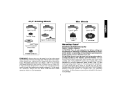
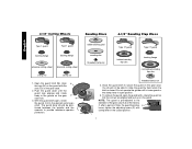
.... I ) into the desired working po sition. You should be able to secure the guard on the guard. 4-1/2" Cutting Wheels Sanding Discs 4-1/2" Sanding Flap Discs English Type 1 guard backing flange Type 1 guard backing flange abrasive cutting wheel diamond cutting wheel clamp nut clamp nut 1. rubber backing pad sanding disc threaded clamp nut...
.... I ) into the desired working po sition. You should be able to secure the guard on the guard. 4-1/2" Cutting Wheels Sanding Discs 4-1/2" Sanding Flap Discs English Type 1 guard backing flange Type 1 guard backing flange abrasive cutting wheel diamond cutting wheel clamp nut clamp nut 1. rubber backing pad sanding disc threaded clamp nut...
Instruction Manual
Page 9
Align the lugs (N) on the guard with Type 27 wheels designed and specified for at start unexpectedly when it may burst and cause injury. Push the guard down . The guard body should be ... switch is laid down . Lift the tool from the surface before laying the tool down . 8 PADDLE SWITCH (D28402, D28402N) CAUTION: Before connecting the tool to a power source depress and release the paddle switch (A) once [D28402: without depress- Depress and release the paddle switch as described above listed minimum wheel speed as the...
Align the lugs (N) on the guard with Type 27 wheels designed and specified for at start unexpectedly when it may burst and cause injury. Push the guard down . The guard body should be ... switch is laid down . Lift the tool from the surface before laying the tool down . 8 PADDLE SWITCH (D28402, D28402N) CAUTION: Before connecting the tool to a power source depress and release the paddle switch (A) once [D28402: without depress- Depress and release the paddle switch as described above listed minimum wheel speed as the...
Instruction Manual
Page 11
...While depressing the spindle lock but- Apply minimum pressure to the work or deep grinding. Install the unthreaded backing flange D (G) on spindle (D) with a Type 1 cut -off work surface, allowing the tool to do cut -off . To remove the wheel, depress the spindle lock button and loosen the threaded ... before turning tool off wheel, use of these wheels with included flanges. If the wheel you are installing is being used with a standard Type 27 guard to shallow cutting and notching (less than 1/8" (3.31mm) thick, place the threaded clamp nut on the clamp nut against the ...
...While depressing the spindle lock but- Apply minimum pressure to the work or deep grinding. Install the unthreaded backing flange D (G) on spindle (D) with a Type 1 cut -off work surface, allowing the tool to do cut -off . To remove the wheel, depress the spindle lock button and loosen the threaded ... before turning tool off wheel, use of these wheels with included flanges. If the wheel you are installing is being used with a standard Type 27 guard to shallow cutting and notching (less than 1/8" (3.31mm) thick, place the threaded clamp nut on the clamp nut against the ...
Instruction Manual
Page 13
... brushes and wheels. MOUNTING WIRE CUP BRUSHES AND WIRE WHEELS CAUTION: Turn off . Material removal rate is greatest when the tool operates at high speed. A Type 27 guard is off . Remove the tool from the work surface. 4. CAUTION: Use extra care when working over an edge, as previously described to prevent...
... brushes and wheels. MOUNTING WIRE CUP BRUSHES AND WIRE WHEELS CAUTION: Turn off . Material removal rate is greatest when the tool operates at high speed. A Type 27 guard is off . Remove the tool from the work surface. 4. CAUTION: Use extra care when working over an edge, as previously described to prevent...
Instruction Manual
Page 14
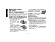
...wheel, grasp and turn the switch on and off . 1. Diamond blades for more information. WARNING: A closed position. MOUNTING CLOSED (TYPE 1) GUARD CAUTION: Turn off and unplug the tool before making any adjustments or removing or installing attachments or acces- You should be ...included with clamp lever in the P closed position. Failure to guard or mounting hub may result. English Mounting and Using Cutting (Type 1) Wheels Cutting wheels include diamond wheels and abrasive discs. Before reconnecting the tool, turn while depressing the spindle lock button. 13...
...wheel, grasp and turn the switch on and off . 1. Diamond blades for more information. WARNING: A closed position. MOUNTING CLOSED (TYPE 1) GUARD CAUTION: Turn off and unplug the tool before making any adjustments or removing or installing attachments or acces- You should be ...included with clamp lever in the P closed position. Failure to guard or mounting hub may result. English Mounting and Using Cutting (Type 1) Wheels Cutting wheels include diamond wheels and abrasive discs. Before reconnecting the tool, turn while depressing the spindle lock button. 13...
Parts Diagram
Page 2
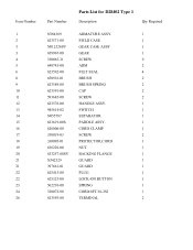
Item Number 1 2 3 3 4 5 6 8 9 10 11 12 13 14 15 16 17 18 19 20 21 21 22 22 23 24 26 Part Number Parts List for D28402 Type 1 Description Qty Required N384369 ARMATURE ASSY. 1 623571-00 FIELD CASE 1 N012328SV GEAR CASE ASSY 1 659967-00 GEAR 1 330065-31 SCREW 9 648743-00 ARM 2 623592-00 ...
Item Number 1 2 3 3 4 5 6 8 9 10 11 12 13 14 15 16 17 18 19 20 21 21 22 22 23 24 26 Part Number Parts List for D28402 Type 1 Description Qty Required N384369 ARMATURE ASSY. 1 623571-00 FIELD CASE 1 N012328SV GEAR CASE ASSY 1 659967-00 GEAR 1 330065-31 SCREW 9 648743-00 ARM 2 623592-00 ...
Parts Diagram
Page 3
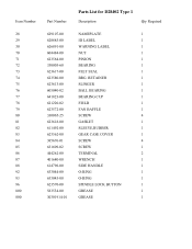
... 623562-00 385676-01 631609-02 444262-00 401680-00 614796-00 633044-00 633043-00 623570-00 583534-00 30301914-01 Parts List for D28402 Type 1 Description Qty Required NAMEPLATE 1 ID LABEL 1 WARNING LABEL 1 NUT 1 PINION 1 BEARING 1 FELT SEAL 1 BRG. RETAINER 1 SLINGER 1 BALL BEARING 1 BEARING CUP 1 FIELD 1 FAN BAFFLE 1 SCREW 4 GASKET...
... 623562-00 385676-01 631609-02 444262-00 401680-00 614796-00 633044-00 633043-00 623570-00 583534-00 30301914-01 Parts List for D28402 Type 1 Description Qty Required NAMEPLATE 1 ID LABEL 1 WARNING LABEL 1 NUT 1 PINION 1 BEARING 1 FELT SEAL 1 BRG. RETAINER 1 SLINGER 1 BALL BEARING 1 BEARING CUP 1 FIELD 1 FAN BAFFLE 1 SCREW 4 GASKET...
Parts Diagram
Page 4
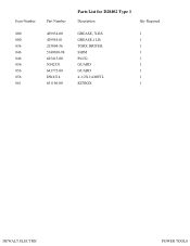
Item Number 800 800 836 846 846 856 856 856 861 Part Number 429954-00 429954-01 233804-36 5140030-98 625415-00 N342331 643772-00 DW4514 651196-00 Parts List for D28402 Type 1 Description Qty Required GREASE, 7LBS 1 GREASE,1 LB. 1 TORX DRIVER 1 SHIM 1 PLUG 1 GUARD 1 GUARD 1 4-1/2X1/4 METL 1 KITBOX 1 DEWALT ELECTRIC POWER TOOLS
Item Number 800 800 836 846 846 856 856 856 861 Part Number 429954-00 429954-01 233804-36 5140030-98 625415-00 N342331 643772-00 DW4514 651196-00 Parts List for D28402 Type 1 Description Qty Required GREASE, 7LBS 1 GREASE,1 LB. 1 TORX DRIVER 1 SHIM 1 PLUG 1 GUARD 1 GUARD 1 4-1/2X1/4 METL 1 KITBOX 1 DEWALT ELECTRIC POWER TOOLS


