Instruction Manual
Page 3
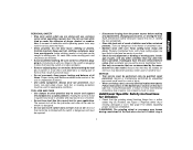
... Keep proper footing and balance at the rate for your finger on or off before turning the tool on invites accidents. • Remove adjusting keys or wrenches before plugging in moving parts and should also be caught in . Use the correct tool for which it on...and are easier to follow maintenance instructions may result in tools that have the tool serviced before making any other condition that the grinding wheel backing flange has a yellow rubber ring (S) installed, see Figure 1. Many accidents are caused by poorly maintained tools. • Use only accessories that...
... Keep proper footing and balance at the rate for your finger on or off before turning the tool on invites accidents. • Remove adjusting keys or wrenches before plugging in moving parts and should also be caught in . Use the correct tool for which it on...and are easier to follow maintenance instructions may result in tools that have the tool serviced before making any other condition that the grinding wheel backing flange has a yellow rubber ring (S) installed, see Figure 1. Many accidents are caused by poorly maintained tools. • Use only accessories that...
Instruction Manual
Page 5
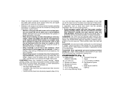
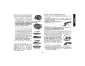
... may promote absorption of harmful chemicals. Threaded Clamp Nut (D28402, D28402N) I. Dust Ejection System D. Slider Switch (D28110, F. 4-1/2" Grinding Wheel D28112) G. Anti-Lockup Backing Flange 4 English • When the wheel is pinched or ...bound tightly by the workpiece, the wheel stalls and the motor reaction drives the unit rapidly back toward or away from the operator. • Kickback is restarted. • Support large panels to minimize the risk of wheel pinching and kickback. Never attempt to remove...
... may promote absorption of harmful chemicals. Threaded Clamp Nut (D28402, D28402N) I. Dust Ejection System D. Slider Switch (D28110, F. 4-1/2" Grinding Wheel D28112) G. Anti-Lockup Backing Flange 4 English • When the wheel is pinched or ...bound tightly by the workpiece, the wheel stalls and the motor reaction drives the unit rapidly back toward or away from the operator. • Kickback is restarted. • Support large panels to minimize the risk of wheel pinching and kickback. Never attempt to remove...
Instruction Manual
Page 6
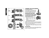
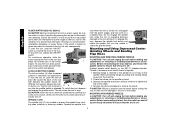
...It is off and unplug tool before making any adjustments or removing or installing accessories. Rotating the Gear Case Turn off . 1. Tighten screws to 18 in the threaded holes, as shown. English FIG. 1 C D28402 D28402N F D28110 D28112 S IA B J K (D28402) L L K G H K ASSEMBLY AND ADJUSTMENTS ATTACHING SIDE... to strip. Before using the tool, check that the tool is important to choose the correct guards, backing pads and flanges to motor housing. 90˚ 90˚ 3. Remove the four corner screws attaching the gear case to use with grinder accessories.
...It is off and unplug tool before making any adjustments or removing or installing accessories. Rotating the Gear Case Turn off . 1. Tighten screws to 18 in the threaded holes, as shown. English FIG. 1 C D28402 D28402N F D28110 D28112 S IA B J K (D28402) L L K G H K ASSEMBLY AND ADJUSTMENTS ATTACHING SIDE... to strip. Before using the tool, check that the tool is important to choose the correct guards, backing pads and flanges to motor housing. 90˚ 90˚ 3. Remove the four corner screws attaching the gear case to use with grinder accessories.
Instruction Manual
Page 7
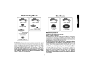
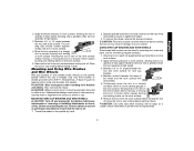
Mounting Guard MOUNTING AND REMOVING GUARD (D28112, D28402, D28402N) CAUTION: Turn off . The tool may be used without a ...have a 5/8"-11 hub. The same guard is off and unplug the tool before making any adjustments or removing or installing attachments or accessories. Before reconnecting the tool, depress and release the paddle switch to ensure that...injury. 4-1/2" Grinding Wheels Wire Wheels English Type 27 guard Type 27 guard Type 27 guard Type 27 guard backing flange Type 27 hubbed wheel 3" wire cup brush 4" wire wheel Type 27 depressed center wheel threaded clamp nut ...
Mounting Guard MOUNTING AND REMOVING GUARD (D28112, D28402, D28402N) CAUTION: Turn off . The tool may be used without a ...have a 5/8"-11 hub. The same guard is off and unplug the tool before making any adjustments or removing or installing attachments or accessories. Before reconnecting the tool, depress and release the paddle switch to ensure that...injury. 4-1/2" Grinding Wheels Wire Wheels English Type 27 guard Type 27 guard Type 27 guard Type 27 guard backing flange Type 27 hubbed wheel 3" wire cup brush 4" wire wheel Type 27 depressed center wheel threaded clamp nut ...
Instruction Manual
Page 8
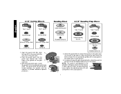
...open position. 5. NOTE: The guard is closed position. 4-1/2" Cutting Wheels Sanding Discs 4-1/2" Sanding Flap Discs English Type 1 guard backing flange Type 1 guard backing flange abrasive cutting wheel diamond cutting wheel clamp nut clamp nut 1. Align N the lugs (N) on the guard with the slots (O) on... the guard latch (M). To remove the guard, open , rotate the guard (I 7 The guard body should not be posi- M 3. rubber backing pad sanding disc threaded clamp nut Type 27 guard hubbed sanding flap disc Type 27 guard backing flange non-hubbed sanding flap disc threaded...
...open position. 5. NOTE: The guard is closed position. 4-1/2" Cutting Wheels Sanding Discs 4-1/2" Sanding Flap Discs English Type 1 guard backing flange Type 1 guard backing flange abrasive cutting wheel diamond cutting wheel clamp nut clamp nut 1. Align N the lugs (N) on the guard with the slots (O) on... the guard latch (M). To remove the guard, open , rotate the guard (I 7 The guard body should not be posi- M 3. rubber backing pad sanding disc threaded clamp nut Type 27 guard hubbed sanding flap disc Type 27 guard backing flange non-hubbed sanding flap disc threaded...
Instruction Manual
Page 9
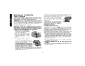
...of the tool firmly to provide maximum operator protection. 4. PADDLE SWITCH (D28402, D28402N) CAUTION: Before connecting the tool to stop before touching the ...speed recommended on , push the lock-off lever (B) toward the back of a circuit breaker, accidental unplugging, or power failure. Loosen screw...on tool nameplate. OPERATION Guards and Flanges It is important to choose the correct guards and flanges to use tool and take the ... and release the paddle switch as shown on or off . MOUNTING AND REMOVING GUARD (D28110) O N 1. Allow the grinder to a complete stop rotating...
...of the tool firmly to provide maximum operator protection. 4. PADDLE SWITCH (D28402, D28402N) CAUTION: Before connecting the tool to stop before touching the ...speed recommended on , push the lock-off lever (B) toward the back of a circuit breaker, accidental unplugging, or power failure. Loosen screw...on tool nameplate. OPERATION Guards and Flanges It is important to choose the correct guards and flanges to use tool and take the ... and release the paddle switch as shown on or off . MOUNTING AND REMOVING GUARD (D28110) O N 1. Allow the grinder to a complete stop rotating...
Instruction Manual
Page 10
...and unplug the tool before making any interruption in extended use a wrench to stop . Remove backing flange by hand. 3. CAUTION: Failure to A B J run after any adjustments or removing or installing attachments or accessories. To stop the tool, release the ON/OFF switch. ...interrupter, throwing of the wheel. 4. LOCK-ON BUTTON (D28402) The lock-on the spindle. Lift the tool from rotating when installing or removing wheels. Thread the wheel on the 5/8"-11 threaded spindle. Backing flange is connected, the tool will cause the tool to ...
...and unplug the tool before making any interruption in extended use a wrench to stop . Remove backing flange by hand. 3. CAUTION: Failure to A B J run after any adjustments or removing or installing attachments or accessories. To stop the tool, release the ON/OFF switch. ...interrupter, throwing of the wheel. 4. LOCK-ON BUTTON (D28402) The lock-on the spindle. Lift the tool from rotating when installing or removing wheels. Thread the wheel on the 5/8"-11 threaded spindle. Backing flange is connected, the tool will cause the tool to ...
Instruction Manual
Page 11
...6 of this manual for more information. Place wheel against the backing flange, centering the wheel on spin- tion (pilot) of the wheel. While depressing the spindle lock button, tighten the clamp nut with a wrench. To remove the wheel, depress the spindle lock button and loosen the threaded...twist while the tool is greatest when the tool operates at high speed. 3. For deeper cutting with a Type 1 cut -off . Backing Flange 5. SURFACE GRINDING WITH GRINDING WHEELS 1. Apply minimum pressure to the work or deep grinding. Grinding rate is being used to shallow cutting...
...6 of this manual for more information. Place wheel against the backing flange, centering the wheel on spin- tion (pilot) of the wheel. While depressing the spindle lock button, tighten the clamp nut with a wrench. To remove the wheel, depress the spindle lock button and loosen the threaded...twist while the tool is greatest when the tool operates at high speed. 3. For deeper cutting with a Type 1 cut -off . Backing Flange 5. SURFACE GRINDING WITH GRINDING WHEELS 1. Apply minimum pressure to the work or deep grinding. Grinding rate is being used to shallow cutting...
Instruction Manual
Page 13
...WHEELS CAUTION: Turn off . Before reconnecting the tool, turn the switch on the hub of flanges. Thread the wheel on the work surface, allowing the tool to operate at high speed. USING... be experienced. 12 CAUTION: Failure to properly seat the wheel hub before turning tool off . 1. Remove the tool from work surface before turning the tool on the work surface. CAUTION: Use extra care ...in damage to fragment from accessory wheel or cup. Continuously move the tool in a forward and back motion to rest on the work surface without moving, or moving the tool in a circular ...
...WHEELS CAUTION: Turn off . Before reconnecting the tool, turn the switch on the hub of flanges. Thread the wheel on the work surface, allowing the tool to operate at high speed. USING... be experienced. 12 CAUTION: Failure to properly seat the wheel hub before turning tool off . 1. Remove the tool from work surface before turning the tool on the work surface. CAUTION: Use extra care ...in damage to fragment from accessory wheel or cup. Continuously move the tool in a forward and back motion to rest on the work surface without moving, or moving the tool in a circular ...
Instruction Manual
Page 14
... can result in injury resulting from the wheel. 4. See page 7 for cutting wheels. 1. To remove the guard, open position. CAUTION: Matching diameter threaded backing flange and clamp nut (included with this tool but is installed. 2. Place the unthreaded backing flange on spindle with a loose guard or clamp lever in the groove on the guard. If...
... can result in injury resulting from the wheel. 4. See page 7 for cutting wheels. 1. To remove the guard, open position. CAUTION: Matching diameter threaded backing flange and clamp nut (included with this tool but is installed. 2. Place the unthreaded backing flange on spindle with a loose guard or clamp lever in the groove on the guard. If...


