
Operating Instructions
Page 6
...Output The crossfader adjustment is on every input channel. 7. In the OFF mode, the Mic signal will not be used when the DENON CD players DN-D4500 or etc. Only DN-X900 : FLEX FADER (Adjustable Slide Torque Crossfader.) The crossfader's ...FADER START A A B ON OFF CROSS FADER START B DIGITAL OUT CH FADER START ON OFF CUE MASTER PAN 234 1 MASTER BOOTH ASSIGN 0 10 LEVEL 0 10 BOOTH LEVEL BOOTH 3 4 MAIN MIC 2 AUX MIC 1 MASTER OFF EFFECT ASSIGN L R BALANCE MASTER CUE ON/OFF DRY WET EFFECT LOOP EFFECTS 0 10 LEVEL ZONE 0 10 LEVEL SPLIT CUE PHONES DJ MIXER...
...Output The crossfader adjustment is on every input channel. 7. In the OFF mode, the Mic signal will not be used when the DENON CD players DN-D4500 or etc. Only DN-X900 : FLEX FADER (Adjustable Slide Torque Crossfader.) The crossfader's ...FADER START A A B ON OFF CROSS FADER START B DIGITAL OUT CH FADER START ON OFF CUE MASTER PAN 234 1 MASTER BOOTH ASSIGN 0 10 LEVEL 0 10 BOOTH LEVEL BOOTH 3 4 MAIN MIC 2 AUX MIC 1 MASTER OFF EFFECT ASSIGN L R BALANCE MASTER CUE ON/OFF DRY WET EFFECT LOOP EFFECTS 0 10 LEVEL ZONE 0 10 LEVEL SPLIT CUE PHONES DJ MIXER...

Operating Instructions
Page 7
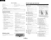
...unbalanced RCA jacks are Inputs for any line level device. $4 LINE 2, 4, 6, 8 FADER output jacks • Connect these jacks to connect the ground wire from the selected sources. @7 CROSSFADER ASSIGN switch A, B: • The channel source is assigned to the right. • In the STEREO mode, the meter indicates ... OUT ON/OFF switch • When this switch is on an amplifier or console. • Pin layout: Tip: Hot, Ring: Cold, Sleeve: GND (DNX500) • Pin layout: 1. Zone Level controls and are connected to switch the Crossfader Start fuction ON and OFF. #2 CH. Tip: Send Ring: Return...
...unbalanced RCA jacks are Inputs for any line level device. $4 LINE 2, 4, 6, 8 FADER output jacks • Connect these jacks to connect the ground wire from the selected sources. @7 CROSSFADER ASSIGN switch A, B: • The channel source is assigned to the right. • In the STEREO mode, the meter indicates ... OUT ON/OFF switch • When this switch is on an amplifier or console. • Pin layout: Tip: Hot, Ring: Cold, Sleeve: GND (DNX500) • Pin layout: 1. Zone Level controls and are connected to switch the Crossfader Start fuction ON and OFF. #2 CH. Tip: Send Ring: Return...

Operating Instructions
Page 10
...8 LINE 2 LINE 4 LINE 6 LINE 8 DN-X500/X900 Turn on CD player. 6 Use the CROSSFADER CONTOUR control @9 to control the cross fader startup curve. Channel Fader Start Turn the INPUT ASSIGN switch !2 to the 3 bottom. 4 Set the standby mode on CD player. Turn on the CROSSFADER START A, B switches...the CROSSFADER ASSIGN switch @,7 assign the channel or 2 Sampler source into A or B of CH-1, CH-2, CH-3 or CH-4 control all the way in the opposite direction, CD player play will begin . 7 5 ENGLISH When the Crossfader @8 is 2 POST) FADER FADER FADER FADER MAIN ALPHA MAIN ALPHA MAIN ALPHA MAIN...
...8 LINE 2 LINE 4 LINE 6 LINE 8 DN-X500/X900 Turn on CD player. 6 Use the CROSSFADER CONTOUR control @9 to control the cross fader startup curve. Channel Fader Start Turn the INPUT ASSIGN switch !2 to the 3 bottom. 4 Set the standby mode on CD player. Turn on the CROSSFADER START A, B switches...the CROSSFADER ASSIGN switch @,7 assign the channel or 2 Sampler source into A or B of CH-1, CH-2, CH-3 or CH-4 control all the way in the opposite direction, CD player play will begin . 7 5 ENGLISH When the Crossfader @8 is 2 POST) FADER FADER FADER FADER MAIN ALPHA MAIN ALPHA MAIN ALPHA MAIN...
Operating Instructions
Page 11
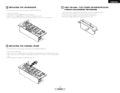
... screws B attaching the crossfader bracket assembly from the front panel. 3. Pull out the channel fader knob. 2. A 6 ENGLISH Remove the two outer screws A attaching the channel fader plate and channel fader bracket assembly from chassis. 4. Move the lever so that the head of the screw ...crossfader from the set. 2. Pull the channel fader bracket assembly forward and unplug the 3P cable from the connector on the channel fader printing board. 4. Pull out the crossfader knob. 2. A B ENGLISH 8 ONLY DN-X900 : FLEX FADER CROSSFADER SLIDE TORQUE ADJUSTMENT PROCEDURE 1. 6 ...
... screws B attaching the crossfader bracket assembly from the front panel. 3. Pull out the channel fader knob. 2. A 6 ENGLISH Remove the two outer screws A attaching the channel fader plate and channel fader bracket assembly from chassis. 4. Move the lever so that the head of the screw ...crossfader from the set. 2. Pull the channel fader bracket assembly forward and unplug the 3P cable from the connector on the channel fader printing board. 4. Pull out the crossfader knob. 2. A B ENGLISH 8 ONLY DN-X900 : FLEX FADER CROSSFADER SLIDE TORQUE ADJUSTMENT PROCEDURE 1. 6 ...
