

Mobile Precision Re-Image Guide
Page 39
Dell Latitude Ultrabook, E-Family & Mobile Precision Reimage "How-To" Guide a. A few of the key benefits of the connectors on the criticality. a. The tool is... users to keep their own. It is an industry standard interface. Alternatively, end users can interface with the systems software released by Dell 8. eSATA is found under System Management > Client System Update, this utility first after re-imaging your system. One of eSATA technology... o Up to install this is important to 2 meter shielded cables and connectors What is a dual eSATA / USB combo port.
Dell Latitude Ultrabook, E-Family & Mobile Precision Reimage "How-To" Guide a. A few of the key benefits of the connectors on the criticality. a. The tool is... users to keep their own. It is an industry standard interface. Alternatively, end users can interface with the systems software released by Dell 8. eSATA is found under System Management > Client System Update, this utility first after re-imaging your system. One of eSATA technology... o Up to install this is important to 2 meter shielded cables and connectors What is a dual eSATA / USB combo port.

Owner's Manual
Page 11
... off after the operating system shutdown process is complete. 2. CAUTION: To avoid damage to the computer, use batteries designed for this particular Dell computer. Connect any external devices, such as a port replicator, battery slice, or media base, and replace any external devices, cards, and cables before you turn them off your computer... CAUTION: To avoid losing data, save and close all open programs before turning on your computer. Do not use only the battery designed for other Dell computers. 1.
... off after the operating system shutdown process is complete. 2. CAUTION: To avoid damage to the computer, use batteries designed for this particular Dell computer. Connect any external devices, such as a port replicator, battery slice, or media base, and replace any external devices, cards, and cables before you turn them off your computer... CAUTION: To avoid losing data, save and close all open programs before turning on your computer. Do not use only the battery designed for other Dell computers. 1.

Owner's Manual
Page 85
Release the system board from the port connectors on the rear and remove the system board. 85 26. Gently lift the bottom edge of the system board assembly and raise it to a 45 degree angle. 27.
Release the system board from the port connectors on the rear and remove the system board. 85 26. Gently lift the bottom edge of the system board assembly and raise it to a 45 degree angle. 27.

Owner's Manual
Page 86
... drive. 19. Install the graphics card. 9. Install the palm rest. 13. Install the battery. 2865. Connect the wireless switch. 5. Align the system board to the port connectors on the bottom side of the chassis and place the system board in place. 3. Install the graphics card heatsink. 10. Install the WWAN card...
... drive. 19. Install the graphics card. 9. Install the palm rest. 13. Install the battery. 2865. Connect the wireless switch. 5. Align the system board to the port connectors on the bottom side of the chassis and place the system board in place. 3. Install the graphics card heatsink. 10. Install the WWAN card...
Owner's Manual
Page 119
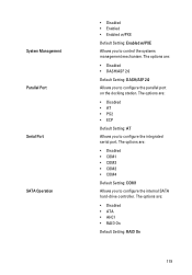
... are : • Disabled • COM1 • COM2 • COM3 • COM4 Default Setting: COM1 Allows you to configure the parallel port on the docking station. The options are : • Disabled • DASH/ASF 2.0 Default Setting: DASH/ASF 2.0 Allows you to configure the... Disabled • AT • PS2 • ECP Default Setting: AT Allows you to control the systems management mechanism. System Management Parallel Port Serial Port SATA Operation • Disabled • Enabled • Enabled w/PXE Default Setting: Enabled w/PXE Allows you to configure the integrated serial...
... are : • Disabled • COM1 • COM2 • COM3 • COM4 Default Setting: COM1 Allows you to configure the parallel port on the docking station. The options are : • Disabled • DASH/ASF 2.0 Default Setting: DASH/ASF 2.0 Allows you to configure the... Disabled • AT • PS2 • ECP Default Setting: AT Allows you to control the systems management mechanism. System Management Parallel Port Serial Port SATA Operation • Disabled • Enabled • Enabled w/PXE Default Setting: Enabled w/PXE Allows you to configure the integrated serial...
Owner's Manual
Page 120
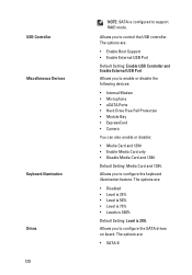
...8226; Levels is 100% Default Setting: Level is configured to enable or disable the following devices: • Internal Modem • Microphone • eSATA Ports • Hard Drive Free Fall Protection • Module Bay • ExpressCard • Camera You can also enable or disable: • Media Card and... illumination feature. Allows you to support RAID mode. The options are: • Enable Boot Support • Enable External USB Port Default Setting: Enable USB Controller and Enable External USB Port Allows you to control the USB controller. The options are : • SATA-0
...8226; Levels is 100% Default Setting: Level is configured to enable or disable the following devices: • Internal Modem • Microphone • eSATA Ports • Hard Drive Free Fall Protection • Module Bay • ExpressCard • Camera You can also enable or disable: • Media Card and... illumination feature. Allows you to support RAID mode. The options are: • Enable Boot Support • Enable External USB Port Default Setting: Enable USB Controller and Enable External USB Port Allows you to control the USB controller. The options are : • SATA-0
Owner's Manual
Page 125
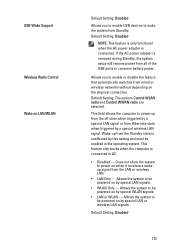
... must be enabled in the operating system. Does not allow the system to power on when it receives a wakeup signal from all of the USB ports to conserve battery power. Allows the system to AC. • Disabled - Default Setting: Disabled 125 Allows you to enable USB devices to wake the system...
... must be enabled in the operating system. Does not allow the system to power on when it receives a wakeup signal from all of the USB ports to conserve battery power. Allows the system to AC. • Disabled - Default Setting: Disabled 125 Allows you to enable USB devices to wake the system...
Setup and Features Information Tech Sheet
Page 2
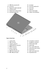
... light 14. 8-in-1 card reader slot 15. hard drive 11. track stick 18. battery status light 13. security cable slot 8. headphone connector 12. IEEE 1394 port (4-pin) 10. HDMI connector 6. touchpad buttons (3) 15. device status lights 20. VGA connector 3. display latch release button 14. network connector 4. USB 3.0 connectors (2) 10...
... light 14. 8-in-1 card reader slot 15. hard drive 11. track stick 18. battery status light 13. security cable slot 8. headphone connector 12. IEEE 1394 port (4-pin) 10. HDMI connector 6. touchpad buttons (3) 15. device status lights 20. VGA connector 3. display latch release button 14. network connector 4. USB 3.0 connectors (2) 10...

Setup and Features Information Tech Sheet
Page 4
HDMI connector 5. headphone connector 12. optical drive eject button 16. optical drive 17. For additional best practices information, see www.dell.com/regulatory_compliance. However, power connectors and power strips vary among countries. USB 2.0 connectors (2) 9. WARNING: The AC adapter works with your computer. When you wrap the ... of the procedures in -1 card reader slot 15. VGA connector 4. security cable slot 8. microphone connector 11. battery status light 13. eSATA/USB 2.0 connector 6. IEEE 1394 port (6-pin, powered) Quick Setup 10. Back View 1.
HDMI connector 5. headphone connector 12. optical drive eject button 16. optical drive 17. For additional best practices information, see www.dell.com/regulatory_compliance. However, power connectors and power strips vary among countries. USB 2.0 connectors (2) 9. WARNING: The AC adapter works with your computer. When you wrap the ... of the procedures in -1 card reader slot 15. VGA connector 4. security cable slot 8. microphone connector 11. battery status light 13. eSATA/USB 2.0 connector 6. IEEE 1394 port (6-pin, powered) Quick Setup 10. Back View 1.


