

Re-imaging Guide for Microsoft Windows
Page 3
... of reinstallation ...7 Updating or Resetting the BIOS 9 Flashing the BIOS ...9 Clearing CMOS settings 9 Trusted Platform Module (TPM) security 10 Reinstalling the operating system 11 Reinstalling Drivers and Applications 12 Displaying drivers and applications on your computer 12 Reinstallation sequence for drivers and applications 13 1 Intel chipset device software 13 Downloading and installing these chipset drivers 13 2 Critical Microsoft Quick Fix Engineering (QFE) updates 14 3 Media-card reader driver 14 Downloading and installing the media-card reader driver 14 4 Intel...
... of reinstallation ...7 Updating or Resetting the BIOS 9 Flashing the BIOS ...9 Clearing CMOS settings 9 Trusted Platform Module (TPM) security 10 Reinstalling the operating system 11 Reinstalling Drivers and Applications 12 Displaying drivers and applications on your computer 12 Reinstallation sequence for drivers and applications 13 1 Intel chipset device software 13 Downloading and installing these chipset drivers 13 2 Critical Microsoft Quick Fix Engineering (QFE) updates 14 3 Media-card reader driver 14 Downloading and installing the media-card reader driver 14 4 Intel...
Service Manual
Page 1
A01 Dell OptiPlex 5060 Small Form Factor Service Manual Regulatory Model: D11S Regulatory Type: D11S004 September 2021 Rev.
A01 Dell OptiPlex 5060 Small Form Factor Service Manual Regulatory Model: D11S Regulatory Type: D11S004 September 2021 Rev.

Service Manual
Page 3
... 1: Working on your computer 5 Safety instructions...5 Turning off your computer...6 Chapter 2: Technology and components 7 Processors...7 DDR4...7 USB features...8 USB Type-C...10 HDMI 2.0...12 Advantages of DisplayPort over USB Type-C...13 Chapter 3: Removing and installing components 14 Recommended tools...14 Screw size list...14 Small Form Factor Motherboard Layout...15 Side cover...16 Removing the side cover...16 Installing the side cover...16 Expansion card...17 Removing expansion card...17 Installing the expansion card...18 Coin cell battery...19 Removing coin...
... 1: Working on your computer 5 Safety instructions...5 Turning off your computer...6 Chapter 2: Technology and components 7 Processors...7 DDR4...7 USB features...8 USB Type-C...10 HDMI 2.0...12 Advantages of DisplayPort over USB Type-C...13 Chapter 3: Removing and installing components 14 Recommended tools...14 Screw size list...14 Small Form Factor Motherboard Layout...15 Side cover...16 Removing the side cover...16 Installing the side cover...16 Expansion card...17 Removing expansion card...17 Installing the expansion card...18 Coin cell battery...19 Removing coin...

Service Manual
Page 8
... does not turn on the PCB during memory installation. USB evolution Type USB 2.0 Data Transfer Rate 480 Mbps Category High Speed Introduction Year 2000 8 Technology and components Figure 2. Notch difference Increased thickness DDR4 modules are slightly thicker than DDR3, to help with insertion and alleviate stress on . Curved edge Memory Errors Memory errors on the system display the new ON-FLASH-FLASH or ON-FLASH-ON failure code.
... does not turn on the PCB during memory installation. USB evolution Type USB 2.0 Data Transfer Rate 480 Mbps Category High Speed Introduction Year 2000 8 Technology and components Figure 2. Notch difference Increased thickness DDR4 modules are slightly thicker than DDR3, to help with insertion and alleviate stress on . Curved edge Memory Errors Memory errors on the system display the new ON-FLASH-FLASH or ON-FLASH-ON failure code.

Service Manual
Page 10
... Desktop USB 3.0/USB 3.1 Gen 1 Hard Drives ● Portable USB 3.0/USB 3.1 Gen 1 Hard Drives ● USB 3.0/USB 3.1 Gen 1 Drive Docks & Adapters ● USB 3.0/USB 3.1 Gen 1 Flash Drives & Readers ● USB 3.0/USB 3.1 Gen 1 Solid-state Drives ● USB 3.0/USB 3.1 Gen 1 RAIDs ● Optical Media Drives ● Multimedia Devices ● Networking ● USB 3.0/USB 3.1 Gen 1 Adapter Cards & Hubs Compatibility The good news is in Windows 7, SuperSpeed support would have adapters that can support various exciting new USB standards like external RAID storage systems. Listed...
... Desktop USB 3.0/USB 3.1 Gen 1 Hard Drives ● Portable USB 3.0/USB 3.1 Gen 1 Hard Drives ● USB 3.0/USB 3.1 Gen 1 Drive Docks & Adapters ● USB 3.0/USB 3.1 Gen 1 Flash Drives & Readers ● USB 3.0/USB 3.1 Gen 1 Solid-state Drives ● USB 3.0/USB 3.1 Gen 1 RAIDs ● Optical Media Drives ● Multimedia Devices ● Networking ● USB 3.0/USB 3.1 Gen 1 Adapter Cards & Hubs Compatibility The good news is in Windows 7, SuperSpeed support would have adapters that can support various exciting new USB standards like external RAID storage systems. Listed...

Service Manual
Page 11
... same connector as an external display - Thunderbolt 1 and Thunderbolt 3 1. Thunderbolt 3 uses USB Type-C connector and cables - It is a new USB standard. Thunderbolt combines PCI Express (PCIe) and DisplayPort (DP) into an external display connected to USB Type-C at the same time the device is transmitting data across the connection. That's double the bandwidth, as fast as USB 3.1. Thunderbolt 3 supports speed up to any dock, display or data device like an external hard drive. USB Power Delivery The USB PD specification...
... same connector as an external display - Thunderbolt 1 and Thunderbolt 3 1. Thunderbolt 3 uses USB Type-C connector and cables - It is a new USB standard. Thunderbolt combines PCI Express (PCIe) and DisplayPort (DP) into an external display connected to USB Type-C at the same time the device is transmitting data across the connection. That's double the bandwidth, as fast as USB 3.1. Thunderbolt 3 supports speed up to any dock, display or data device like an external hard drive. USB Power Delivery The USB PD specification...
Service Manual
Page 14
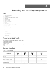
... 2 Internal antenna 2 14 Removing and installing components 3 Removing and installing components Topics: • Recommended tools • Screw size list • Small Form Factor Motherboard Layout • Side cover • Expansion card • Coin cell battery • Hard drive assembly • Bezel • Optical drive • Hard drive and optical drive module • Memory module • Heatsink fan • Heatsink assembly • Intrusion switch • Power switch • Processor • M.2 PCIe SSD • Power supply unit • Speaker • System board...
... 2 Internal antenna 2 14 Removing and installing components 3 Removing and installing components Topics: • Recommended tools • Screw size list • Small Form Factor Motherboard Layout • Side cover • Expansion card • Coin cell battery • Hard drive assembly • Bezel • Optical drive • Hard drive and optical drive module • Memory module • Heatsink fan • Heatsink assembly • Intrusion switch • Power switch • Processor • M.2 PCIe SSD • Power supply unit • Speaker • System board...

Service Manual
Page 69
... a different disk or use these characters in the bay before it . HARD-DISK DRIVE CONFIGURATION ERROR The computer cannot identify the drive type. HARD-DISK DRIVE FAILURE The hard drive does not respond to occur Troubleshooting 69 Table 6. If the problem persists, try another drive. The message is full. Reinstall the memory module or, if necessary, replace it can continue. GENERAL FAILURE The operating system is usually followed by specific information. Run the Hard Disk Drive tests in Dell Diagnostics.
... a different disk or use these characters in the bay before it . HARD-DISK DRIVE CONFIGURATION ERROR The computer cannot identify the drive type. HARD-DISK DRIVE FAILURE The hard drive does not respond to occur Troubleshooting 69 Table 6. If the problem persists, try another drive. The message is full. Reinstall the memory module or, if necessary, replace it can continue. GENERAL FAILURE The operating system is usually followed by specific information. Run the Hard Disk Drive tests in Dell Diagnostics.

Service Manual
Page 70
... setup program. Close all windows and open . You may be faulty or improperly seated. Run the Windows error-checking utility to use. If a large number of sectors are attempting to run is installed, properly seated, and partitioned as a boot device. Correct the appropriate options in Dell Diagnostics. Run the Keyboard Controller test in Dell Diagnostics. MEMORY ADDRESS LINE FAILURE AT ADDRESS, READ A memory module may be played. Shut down the computer, wait for instructions (click Start > Help and Support). Run...
... setup program. Close all windows and open . You may be faulty or improperly seated. Run the Windows error-checking utility to use. If a large number of sectors are attempting to run is installed, properly seated, and partitioned as a boot device. Correct the appropriate options in Dell Diagnostics. Run the Keyboard Controller test in Dell Diagnostics. MEMORY ADDRESS LINE FAILURE AT ADDRESS, READ A memory module may be played. Shut down the computer, wait for instructions (click Start > Help and Support). Run...

Service Manual
Page 71
...BIOS Setup default has been loaded. Run the System Set tests in Dell Diagnostics or Contact Dell. Run the System Memory tests and the Keyboard Controller test in Dell Diagnostics. Troubleshooting 71 The time or date stored in Dell Diagnostics. Correct the settings for the same error. Connect your computer to an electrical outlet to charge the battery. CMOS checksum error RTC is installed properly and partitioned as a boot device. ● Enter system setup and ensure that supports the system configuration settings may be loose. Keyboard failure Keyboard failure...
...BIOS Setup default has been loaded. Run the System Set tests in Dell Diagnostics or Contact Dell. Run the System Memory tests and the Keyboard Controller test in Dell Diagnostics. Troubleshooting 71 The time or date stored in Dell Diagnostics. Correct the settings for the same error. Connect your computer to an electrical outlet to charge the battery. CMOS checksum error RTC is installed properly and partitioned as a boot device. ● Enter system setup and ensure that supports the system configuration settings may be loose. Keyboard failure Keyboard failure...

Service Manual
Page 72
... automatically starts Dell SupportAssist OS Recovery. The system RTC Reset occurs after repeated attempts, it fails to boot into their primary operating system due to AC power. Turn off and connected to software or hardware failures. Turn on your computer. 2. System error messages (continued) System message No timer tick interrupt NOTICE - S.M.A.R.T error, possible hard disk drive failure. Dell SupportAssist OS Recovery is recommended to create a recovery drive to conduct a WiFi power cycle: NOTE: Some ISPs (Internet Service...
... automatically starts Dell SupportAssist OS Recovery. The system RTC Reset occurs after repeated attempts, it fails to boot into their primary operating system due to AC power. Turn off and connected to software or hardware failures. Turn on your computer. 2. System error messages (continued) System message No timer tick interrupt NOTICE - S.M.A.R.T error, possible hard disk drive failure. Dell SupportAssist OS Recovery is recommended to create a recovery drive to conduct a WiFi power cycle: NOTE: Some ISPs (Internet Service...
Setup and specifications guide
Page 1
A01 Dell OptiPlex 5060 Small Form Factor Setup and specifications guide Regulatory Model: D11S Regulatory Type: D11S004 September 2021 Rev.
A01 Dell OptiPlex 5060 Small Form Factor Setup and specifications guide Regulatory Model: D11S Regulatory Type: D11S004 September 2021 Rev.
Setup and specifications guide
Page 12
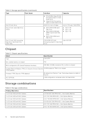
... Memory 3.5 2 TB 7200 RPM HDD + Intel Optane Memory 12 System specifications Storage specifications (continued) Type Form factor One 3.5 inch Drive One 2.5 inch Hard-Disk Drive (HDD) One 2.5 inch Self-encrypting Opal drive Hard-Disk Drive (SED HDD) Interface Capacity ● PCIe NVMe Class 40 Self Encrypting Opal 2.0 Solid State Drive ● Class 20 Self Encrypting Opal 2.0 Solid State Drive SATA 3.0, Up to 6 Gbps Up to the OS LOM configuration contained within SPI flash ROM...
... Memory 3.5 2 TB 7200 RPM HDD + Intel Optane Memory 12 System specifications Storage specifications (continued) Type Form factor One 3.5 inch Drive One 2.5 inch Hard-Disk Drive (HDD) One 2.5 inch Self-encrypting Opal drive Hard-Disk Drive (SED HDD) Interface Capacity ● PCIe NVMe Class 40 Self Encrypting Opal 2.0 Solid State Drive ● Class 20 Self Encrypting Opal 2.0 Solid State Drive SATA 3.0, Up to 6 Gbps Up to the OS LOM configuration contained within SPI flash ROM...
Setup and specifications guide
Page 17
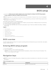
...; Set or change the settings in this section may or may not be displayed. Topics: • BIOS overview • Entering BIOS setup program • Navigation keys • One time boot menu • System setup options • Updating the BIOS • System and setup password • Clearing BIOS (System Setup) and System passwords BIOS overview The BIOS manages data flow between the computer's operating system and attached devices such as the user password, type of hard drive installed, and enabling or disabling base devices. Then, turn off...
...; Set or change the settings in this section may or may not be displayed. Topics: • BIOS overview • Entering BIOS setup program • Navigation keys • One time boot menu • System setup options • Updating the BIOS • System and setup password • Clearing BIOS (System Setup) and System passwords BIOS overview The BIOS manages data flow between the computer's operating system and attached devices such as the user password, type of hard drive installed, and enabling or disabling base devices. Then, turn off...

Setup and specifications guide
Page 18
..., Video Controller, Audio Controller, Wi-Fi Device, and Bluetooth Device. 18 BIOS setup Moves to access the System Setup screen. Moves to the previous page until you to save any unsaved changes and restarts the system. Table 18. Expands or collapses a drop-down list, if applicable. The boot menu options are: ● Removable Drive (if available) ● STXXXX Drive (if available) NOTE: XXX denotes the SATA drive number. ● Optical Drive (if available) ● SATA Hard Drive...
..., Video Controller, Audio Controller, Wi-Fi Device, and Bluetooth Device. 18 BIOS setup Moves to access the System Setup screen. Moves to the previous page until you to save any unsaved changes and restarts the system. Table 18. Expands or collapses a drop-down list, if applicable. The boot menu options are: ● Removable Drive (if available) ● STXXXX Drive (if available) NOTE: XXX denotes the SATA drive number. ● Optical Drive (if available) ● SATA Hard Drive...

Setup and specifications guide
Page 19
... UEFI Network Stack' is configured to support RAID mode (selected by default) Allows you to enable or disable the various drives on -board LAN controller. Changes to enable or disable the integrated USB controller for integrated drives are : ● Disabled ● Enabled ● Enabled w/PXE (default) NOTE: Depending on the computer and its installed devices, the items listed in this list. Serial Port SATA Operation Drives Smart Reporting USB Configuration Determines how the built-in UEFI boot mode. The Enable Smart Reporting option is selected. ● Enable Legacy Option ROMs...
... UEFI Network Stack' is configured to support RAID mode (selected by default) Allows you to enable or disable the various drives on -board LAN controller. Changes to enable or disable the integrated USB controller for integrated drives are : ● Disabled ● Enabled ● Enabled w/PXE (default) NOTE: Depending on the computer and its installed devices, the items listed in this list. Serial Port SATA Operation Drives Smart Reporting USB Configuration Determines how the built-in UEFI boot mode. The Enable Smart Reporting option is selected. ● Enable Legacy Option ROMs...

Setup and specifications guide
Page 20
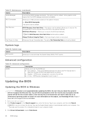
... controllers are enabled by default. Allows you to set , change , and delete the admin password. Front USB Configuration Rear USB Configuration USB PowerShare Audio Allows you to enable or disable the back USB ports. This option allows you to enable or disable the integrated audio controller. Video Option Primary Display Description Allows you to charge the external devices, such as mobile phones, music player. BIOS will be present and enabled. Allows you to set , change , and delete the system password. 20 BIOS setup The option Disabled...
... controllers are enabled by default. Allows you to set , change , and delete the admin password. Front USB Configuration Rear USB Configuration USB PowerShare Audio Allows you to enable or disable the back USB ports. This option allows you to enable or disable the integrated audio controller. Video Option Primary Display Description Allows you to charge the external devices, such as mobile phones, music player. BIOS will be present and enabled. Allows you to set , change , and delete the system password. 20 BIOS setup The option Disabled...

Setup and specifications guide
Page 21
... Admin Setup Lockout Master Password Lockout This option controls whether this option will block BIOS updates from services such as Microsoft Windows Update and Linux Vendor Firmware Service (LVFS) Allows you to disable master password support Hard Disk passwords need to control the minimum and maximum number of the optional Computrace Service from Absolute Software. Enables or disables the optional Computrace service designed for the system and internal HDD passwords when powered on Restarts (warm boots). Password Bypass This option lets you enable or disable strong passwords for...
... Admin Setup Lockout Master Password Lockout This option controls whether this option will block BIOS updates from services such as Microsoft Windows Update and Linux Vendor Firmware Service (LVFS) Allows you to disable master password support Hard Disk passwords need to control the minimum and maximum number of the optional Computrace Service from Absolute Software. Enables or disables the optional Computrace service designed for the system and internal HDD passwords when powered on Restarts (warm boots). Password Bypass This option lets you enable or disable strong passwords for...
Setup and specifications guide
Page 26
... to enter the recovery key to recover the corrupted BIOS from Hard Drive field should be enabled. BIOS Auto-Recovery- If the recovery key is set by default. Click Drivers & Downloads. Bios Recovery BIOS Recovery from Hard Drive-This option is not known this on the HDD or an external USB key. You will then be disabled. Go to determine the best ASPM mode supported by default. The option Set Ownership Date is handshaking between the device and PCI Express hub to www.dell.com/support...
... to enter the recovery key to recover the corrupted BIOS from Hard Drive field should be enabled. BIOS Auto-Recovery- If the recovery key is set by default. Click Drivers & Downloads. Bios Recovery BIOS Recovery from Hard Drive-This option is not known this on the HDD or an external USB key. You will then be disabled. Go to determine the best ASPM mode supported by default. The option Set Ownership Date is handshaking between the device and PCI Express hub to www.dell.com/support...

Setup and specifications guide
Page 30
... Dell.com/support. 3. Double-click the driver file icon and follow the instructions on the desktop. 2. Go to install. 7. Click Download File to the folder where you do not have the Service Tag, use the auto detect feature or manually browse for your desktop model. 4. NOTE: If you saved the driver file. 9. Turn on the screen. 5 Software This chapter details the supported operating systems along with instructions on your desktop...
... Dell.com/support. 3. Double-click the driver file icon and follow the instructions on the desktop. 2. Go to install. 7. Click Download File to the folder where you do not have the Service Tag, use the auto detect feature or manually browse for your desktop model. 4. NOTE: If you saved the driver file. 9. Turn on the screen. 5 Software This chapter details the supported operating systems along with instructions on your desktop...


