
Inspiron 3647 Owners Manual
Page 7
.... • Windows 7 - NOTE: If you turn off your computer. 1 Save and close all open files and exit all open programs before you are using a different operating system, see the documentation of the screen to ground the system board. Before You Begin CAUTION: To avoid losing data, save and close all open files and exit all telephone cables, network cables, and attached devices from...
.... • Windows 7 - NOTE: If you turn off your computer. 1 Save and close all open files and exit all open programs before you are using a different operating system, see the documentation of the screen to ground the system board. Before You Begin CAUTION: To avoid losing data, save and close all open files and exit all telephone cables, network cables, and attached devices from...

Inspiron 3647 Owners Manual
Page 8
... touch an unpainted metal surface to the power source. CAUTION: To avoid damaging the components and cards, handle them evenly aligned to protect your computer from the media-card reader. See the safety instructions for complete information about safety precautions, working inside the computer. When connecting cables, make sure that the connectors and ports are correctly oriented and aligned. Recommended Tools The procedures...
... touch an unpainted metal surface to the power source. CAUTION: To avoid damaging the components and cards, handle them evenly aligned to protect your computer from the media-card reader. See the safety instructions for complete information about safety precautions, working inside the computer. When connecting cables, make sure that the connectors and ports are correctly oriented and aligned. Recommended Tools The procedures...
Inspiron 3647 Owners Manual
Page 22
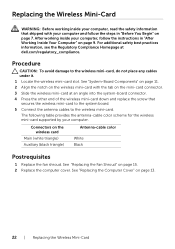
Replacing the Wireless Mini-Card WARNING: Before working inside your computer, read the safety information that secures the wireless mini-card to the system board. 5 Connect the antenna cables to the wireless mini-card, do not place any cables under it. 1 Locate the wireless mini-card slot. For additional safety best practices information, see the Regulatory Compliance Homepage at an angle into the system-board connector. 4 Press the other end...
Replacing the Wireless Mini-Card WARNING: Before working inside your computer, read the safety information that secures the wireless mini-card to the system board. 5 Connect the antenna cables to the wireless mini-card, do not place any cables under it. 1 Locate the wireless mini-card slot. For additional safety best practices information, see the Regulatory Compliance Homepage at an angle into the system-board connector. 4 Press the other end...

Inspiron 3647 Owners Manual
Page 27
Removing the Drive Cage | 27 See "Removing the Primary Hard-Drive" on the hard drive. 1 23 4 5 1 drive cage 3 optical-drive power cable 5 hard-drive power cable 2 optical-drive data cable 4 hard-drive data cable 4 Lift the drive cage away from the chassis. 5 Remove the optical drive. 2 Disconnect the power and data cables from the connectors on the optical drive. 3 Disconnect the power and data cables from the connectors on page 31. See "Removing the Optical Drive" on page 29. 6 Remove the hard drive.
Removing the Drive Cage | 27 See "Removing the Primary Hard-Drive" on the hard drive. 1 23 4 5 1 drive cage 3 optical-drive power cable 5 hard-drive power cable 2 optical-drive data cable 4 hard-drive data cable 4 Lift the drive cage away from the chassis. 5 Remove the optical drive. 2 Disconnect the power and data cables from the connectors on the optical drive. 3 Disconnect the power and data cables from the connectors on page 31. See "Removing the Optical Drive" on page 29. 6 Remove the hard drive.

Inspiron 3647 Owners Manual
Page 28
... Optical Drive" on page 23. 2 Replace the fan shroud. Postrequisites 1 Replace the front bezel. After working inside your computer, follow the steps in "After Working Inside Your Computer" on page 15. 3 Replace the computer cover. See "Removing the Front Bezel" on page 30. 2 Replace the hard drive. Replacing the Drive Cage WARNING: Before working inside your computer, read the safety information that secure the drive cage to the chassis. 5 Connect the power...
... Optical Drive" on page 23. 2 Replace the fan shroud. Postrequisites 1 Replace the front bezel. After working inside your computer, follow the steps in "After Working Inside Your Computer" on page 15. 3 Replace the computer cover. See "Removing the Front Bezel" on page 30. 2 Replace the hard drive. Replacing the Drive Cage WARNING: Before working inside your computer, read the safety information that secure the drive cage to the chassis. 5 Connect the power...

Inspiron 3647 Owners Manual
Page 31
... not remove the hard drive while the computer is On or in Sleep state. See "Removing the Computer Cover" on page 23. 4 Remove the drive cage. See "Removing the Front Bezel" on page 12. 2 Remove the fan shroud. Procedure 1 Remove the screws that shipped with your computer and follow the instructions in "After Working Inside Your Computer" on page 7. CAUTION: Hard drives are fragile. See "Removing the Drive Cage...
... not remove the hard drive while the computer is On or in Sleep state. See "Removing the Computer Cover" on page 23. 4 Remove the drive cage. See "Removing the Front Bezel" on page 12. 2 Remove the fan shroud. Procedure 1 Remove the screws that shipped with your computer and follow the instructions in "After Working Inside Your Computer" on page 7. CAUTION: Hard drives are fragile. See "Removing the Drive Cage...

Inspiron 3647 Owners Manual
Page 32
... secure the hard-drive brackets to the chassis. See "Replacing the Computer Cover" on page 28. 2 Replace the computer cover. Replacing the Primary Hard-Drive WARNING: Before working inside your computer, read the safety information that secure the primary hard-drive assembly to the primary hard-drive. 3 Slide the primary hard-drive assembly into the chassis. 4 Replace the screws that shipped with your computer and follow the instructions in...
... secure the hard-drive brackets to the chassis. See "Replacing the Computer Cover" on page 28. 2 Replace the computer cover. Replacing the Primary Hard-Drive WARNING: Before working inside your computer, read the safety information that secure the primary hard-drive assembly to the primary hard-drive. 3 Slide the primary hard-drive assembly into the chassis. 4 Replace the screws that shipped with your computer and follow the instructions in...
Inspiron 3647 Owners Manual
Page 35
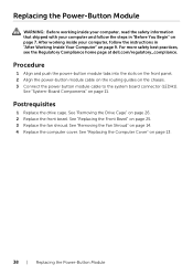
... the slots on the front panel. 2 Slide the front I /O Panel | 35 Ensure that secures the front I/O panel to the front panel. 4 Route the front I/O panel cables through the routing guides on the chassis. 5 Connect the front I/O panel cables to the system-board connectors (USBF1, USBF2, and AUDF1 ). Postrequisites 1 Replace the graphic card, if applicable. See "Replacing the Fan Shroud" on page 19. 2 Replace the drive cage. Replacing the Front I/O Panel WARNING: Before working inside...
... the slots on the front panel. 2 Slide the front I /O Panel | 35 Ensure that secures the front I/O panel to the front panel. 4 Route the front I/O panel cables through the routing guides on the chassis. 5 Connect the front I/O panel cables to the system-board connectors (USBF1, USBF2, and AUDF1 ). Postrequisites 1 Replace the graphic card, if applicable. See "Replacing the Fan Shroud" on page 19. 2 Replace the drive cage. Replacing the Front I/O Panel WARNING: Before working inside...
Inspiron 3647 Owners Manual
Page 38
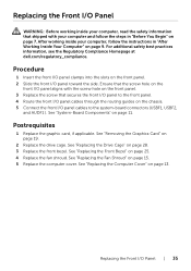
... page 11. Procedure 1 Align and push the power-button module tabs into the slots on the front panel. 2 Align the power-button module cable on the routing guides on page 25. 3 Replace the fan shroud. See "Replacing the Front Bezel" on the chassis. 3 Connect the power button module cable to the system board connector (LEDH1). After working inside your computer and follow the instructions in "Before You Begin" on page 7.
... page 11. Procedure 1 Align and push the power-button module tabs into the slots on the front panel. 2 Align the power-button module cable on the routing guides on page 25. 3 Replace the fan shroud. See "Replacing the Front Bezel" on the chassis. 3 Connect the power button module cable to the system board connector (LEDH1). After working inside your computer and follow the instructions in "Before You Begin" on page 7.
Inspiron 3647 Owners Manual
Page 42
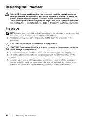
... page 9. Replacing the Processor WARNING: Before working inside your computer, read the safety information that the processor is not fully extended, move it to that position. 3 Orient the alignment notches on the processor with the alignment tabs on the socket. 4 Align the pin-1 corner of the processor with the thermal pad attached to it. 1 Unpack the new processor, being careful...
... page 9. Replacing the Processor WARNING: Before working inside your computer, read the safety information that the processor is not fully extended, move it to that position. 3 Orient the alignment notches on the processor with the alignment tabs on the socket. 4 Align the pin-1 corner of the processor with the thermal pad attached to it. 1 Unpack the new processor, being careful...
Inspiron 3647 Owners Manual
Page 46
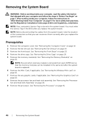
... slot after you replace the system board. You must enter the Service Tag in the BIOS after the system board is stored in the system board. Prerequisites 1 Remove the computer cover. See "Removing the Front Bezel" on page 14. 3 Remove the front bezel. See "Removing the Wireless Mini-card" on page 39. 9 Remove the processor. Removing the System Board WARNING: Before working inside your computer, read the safety information that the memory...
... slot after you replace the system board. You must enter the Service Tag in the BIOS after the system board is stored in the system board. Prerequisites 1 Remove the computer cover. See "Removing the Front Bezel" on page 14. 3 Remove the front bezel. See "Removing the Wireless Mini-card" on page 39. 9 Remove the processor. Removing the System Board WARNING: Before working inside your computer, read the safety information that the memory...

Inspiron 3647 Owners Manual
Page 48
... Board WARNING: Before working inside your computer and follow the instructions in the system board. NOTE: Your computer's Service Tag is displayed to enter System Setup. 3 Navigate to the chassis. 3 Route and connect the cables that shipped with your computer, read the safety information that you replace the system board. See "Replacing the Graphics Card" on page 42. 3 Replace the processor fan and heat sink. Entering the Service Tag in the BIOS 1 Turn...
... Board WARNING: Before working inside your computer and follow the instructions in the system board. NOTE: Your computer's Service Tag is displayed to enter System Setup. 3 Navigate to the chassis. 3 Route and connect the cables that shipped with your computer, read the safety information that you replace the system board. See "Replacing the Graphics Card" on page 42. 3 Replace the processor fan and heat sink. Entering the Service Tag in the BIOS 1 Turn...
Inspiron 3647 Owners Manual
Page 49
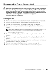
.... 8 Remove the processor. See "Removing the Processor Fan and Heat-Sink Assembly" on page 16. For additional safety best practices information, see the Regulatory Compliance Homepage at dell.com/regulatory_compliance. See "Removing the Graphics Card" on page 12. 2 Remove the fan shroud. Removing the Power-Supply Unit | 49 Removing the Power-Supply Unit WARNING: Before working inside your computer, read the safety information that the memory modules can be installed in...
.... 8 Remove the processor. See "Removing the Processor Fan and Heat-Sink Assembly" on page 16. For additional safety best practices information, see the Regulatory Compliance Homepage at dell.com/regulatory_compliance. See "Removing the Graphics Card" on page 12. 2 Remove the fan shroud. Removing the Power-Supply Unit | 49 Removing the Power-Supply Unit WARNING: Before working inside your computer, read the safety information that the memory modules can be installed in...
Inspiron 3647 Owners Manual
Page 51
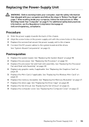
... 22. 6 Replace the memory module(s). See "Replacing the Wireless Mini-Card" on page 11. See "Replacing the Fan Shroud" on page 42. 3 Replace the processor fan and heat-sink assembly. Postrequisites 1 Replace the system board. See "Replacing the Processor" on page 15. 9 Replace the computer cover. See "Replacing the Graphics Card" on page 13. See "Replacing the Computer Cover" on page 20. 5 Replace the Mini-Card, if applicable. Replacing the Power-Supply Unit WARNING: Before working inside your...
... 22. 6 Replace the memory module(s). See "Replacing the Wireless Mini-Card" on page 11. See "Replacing the Fan Shroud" on page 42. 3 Replace the processor fan and heat-sink assembly. Postrequisites 1 Replace the system board. See "Replacing the Processor" on page 15. 9 Replace the computer cover. See "Replacing the Graphics Card" on page 13. See "Replacing the Computer Cover" on page 20. 5 Replace the Mini-Card, if applicable. Replacing the Power-Supply Unit WARNING: Before working inside your...

Inspiron 3647 Owners Manual
Page 52
..., select the operating system installed on your computer. 6 Click BIOS. 7 Click Download File to download the latest version of the Service Tag. Flashing the BIOS You may need to flash (update) the BIOS when an update is complete, navigate to the folder where you saved the BIOS update file. 10 Double-click the BIOS update file icon and follow the instructions on the computer. 2 Go to dell.com/support. 3 If...
..., select the operating system installed on your computer. 6 Click BIOS. 7 Click Download File to download the latest version of the Service Tag. Flashing the BIOS You may need to flash (update) the BIOS when an update is complete, navigate to the folder where you saved the BIOS update file. 10 Double-click the BIOS update file icon and follow the instructions on the computer. 2 Go to dell.com/support. 3 If...
Inspiron 3647 Specifications
Page 2
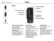
... writes to the hard drive. Hard-drive activity light Turns on . Provides data transfer speeds up to open ) Covers the Front I/O-panel. Optical-drive cover Covers the optical drives. USB 2.0 ports (2) Connect peripherals such as storage devices, printers, and so on the computer if it is turned off or in Sleep state. Specifications Front Views Front Back Front I/O-panel door (open) Media-card reader Headphone port Hard-drive activity light Power button Optical-drive cover Microphone port USB 2.0 ports (2) Optical-drive eject button Back panel Front I/O-panel door (open or close...
... writes to the hard drive. Hard-drive activity light Turns on . Provides data transfer speeds up to open ) Covers the Front I/O-panel. Optical-drive cover Covers the optical drives. USB 2.0 ports (2) Connect peripherals such as storage devices, printers, and so on the computer if it is turned off or in Sleep state. Specifications Front Views Front Back Front I/O-panel door (open) Media-card reader Headphone port Hard-drive activity light Power button Optical-drive cover Microphone port USB 2.0 ports (2) Optical-drive eject button Back panel Front I/O-panel door (open or close...

Inspiron 3647 Specifications
Page 3
Expansion-card slots Provide access to your computer. Back panel Connect USB, audio, video, and other devices. Specifications Back Front Views Expansion-card slots Back Back panel Back panel Security-cable slot Power cable port Power supply light Security-cable slot Connect a security cable to prevent unauthorized movement of the power supply. Power cable port Connect a power cable to provide power to connectors on any installed PCI Express cards. Power supply light Indicates power availability of your computer.
Expansion-card slots Provide access to your computer. Back panel Connect USB, audio, video, and other devices. Specifications Back Front Views Expansion-card slots Back Back panel Back panel Security-cable slot Power cable port Power supply light Security-cable slot Connect a security cable to prevent unauthorized movement of the power supply. Power cable port Connect a power cable to provide power to connectors on any installed PCI Express cards. Power supply light Indicates power availability of your computer.

Inspiron 3647 Specifications
Page 4
...Ethernet (RJ45) cable from a router or a broadband modem for network or internet access. Line-out port Connect speakers. Provides data transfer speeds up to 5 Gbps. Provides video and audio output. HDMI-out port Connect to provide sound input. Provides data transfer speeds up to the connector indicate the connectivity status and network activity. Specifications Views Front Back Back panel Back panel Line-in port Network port Line-out port Microphone port VGA port HDMI-out port USB 3.0 ports (2) USB 2.0 ports (4) Line-in port Connect recording or playback devices...
...Ethernet (RJ45) cable from a router or a broadband modem for network or internet access. Line-out port Connect speakers. Provides data transfer speeds up to 5 Gbps. Provides video and audio output. HDMI-out port Connect to provide sound input. Provides data transfer speeds up to the connector indicate the connectivity status and network activity. Specifications Views Front Back Back panel Back panel Line-in port Network port Line-out port Microphone port VGA port HDMI-out port USB 3.0 ports (2) USB 2.0 ports (4) Line-in port Connect recording or playback devices...
Inspiron 3647 Specifications
Page 6
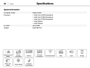
Views System Information Computer model Processor L3 cache Chipset Specifications Inspiron 3647 • Intel Core i3 (4th Generation) • Intel Core i5 (4th Generation) • Intel Core i7 (4th Generation) • Intel Celeron • Intel Pentium up to 8 MB Intel H81 PCH Dimensions and Weight System Information Memory Ports and Connectors Communications Video Media-card reader Power Ratings Computer Environment Audio Storage
Views System Information Computer model Processor L3 cache Chipset Specifications Inspiron 3647 • Intel Core i3 (4th Generation) • Intel Core i5 (4th Generation) • Intel Core i7 (4th Generation) • Intel Celeron • Intel Pentium up to 8 MB Intel H81 PCH Dimensions and Weight System Information Memory Ports and Connectors Communications Video Media-card reader Power Ratings Computer Environment Audio Storage

Inspiron 3647 Specifications
Page 12
Views Storage Externally accessible Internally accessible Specifications One 5.25-inch drive bay for a Blu-ray Disc combo (optional), Blu-ray Disc writer (optional), or DVD+/-RW One 3.5-inch drive bay for SATA hard drives (includes hybrid) Dimensions and Weight System Information Memory Ports and Connectors Communications Video Media-card reader Power Ratings Computer Environment Audio Storage
Views Storage Externally accessible Internally accessible Specifications One 5.25-inch drive bay for a Blu-ray Disc combo (optional), Blu-ray Disc writer (optional), or DVD+/-RW One 3.5-inch drive bay for SATA hard drives (includes hybrid) Dimensions and Weight System Information Memory Ports and Connectors Communications Video Media-card reader Power Ratings Computer Environment Audio Storage


