
Service Manual
Page 1
WE CANNOT GUARANTEE THE ACCURACY OF THIS INFORMATION AFTER THE DATE OF PUBLICATION AND DISCLAIMS RE LIABILITY FOR CHANGES, ERRORS OR OMISSIONS. DELL E173FP Service Manual SERVICE MANUAL 17" LCD Monitor DELL E173FP THESE DOCUMENTS ARE FOR REPAIR SERVICE INFORMATION ONLY. Prepared By: WuHaiyan Checked By: Sushi Manufacture Date: May-29-04 1 EVERY REASONABLE EFFORT HAS BEEN MADE TO ENSURE THE ACCURACY OF THIS MANUAL;
WE CANNOT GUARANTEE THE ACCURACY OF THIS INFORMATION AFTER THE DATE OF PUBLICATION AND DISCLAIMS RE LIABILITY FOR CHANGES, ERRORS OR OMISSIONS. DELL E173FP Service Manual SERVICE MANUAL 17" LCD Monitor DELL E173FP THESE DOCUMENTS ARE FOR REPAIR SERVICE INFORMATION ONLY. Prepared By: WuHaiyan Checked By: Sushi Manufacture Date: May-29-04 1 EVERY REASONABLE EFFORT HAS BEEN MADE TO ENSURE THE ACCURACY OF THIS MANUAL;
Service Manual
Page 2
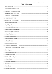
... 18 6.2 Inverter/Power Board 23 2 Block Diagram 13 5.1 Monitor Exploded View 13 5.2 Software Flow Chart 14 5.3 Electrical Block Diagram 16 5.3.1 Main Board 16 5.3.2 Inverter/Power Board 17 6. Input/Output Specification 10 4.1 Input Signal Connector 10 4.1.1 ...Optical Characteristics 12 4.4.4 Parameter guide line for CCFL Inverter 12 5. LCD MONITOR DESCRIPTION 5 3. OPERATING INSTRUCTIONS 6 3.1 GENERAL INSTRUCTIONS 6 3.2 CONTROL BUTTONS 6 3.3 ADJUSTING THE PICTURE 7 4. MONITOR SPECIFICATIONS 4 2. DELL E173FP Service Manual Table of Contents Table of Contents 2 1.
... 18 6.2 Inverter/Power Board 23 2 Block Diagram 13 5.1 Monitor Exploded View 13 5.2 Software Flow Chart 14 5.3 Electrical Block Diagram 16 5.3.1 Main Board 16 5.3.2 Inverter/Power Board 17 6. Input/Output Specification 10 4.1 Input Signal Connector 10 4.1.1 ...Optical Characteristics 12 4.4.4 Parameter guide line for CCFL Inverter 12 5. LCD MONITOR DESCRIPTION 5 3. OPERATING INSTRUCTIONS 6 3.1 GENERAL INSTRUCTIONS 6 3.2 CONTROL BUTTONS 6 3.3 ADJUSTING THE PICTURE 7 4. MONITOR SPECIFICATIONS 4 2. DELL E173FP Service Manual Table of Contents Table of Contents 2 1.
Service Manual
Page 3
DELL E173FP Service Manual 7. Connect ISP Writer preparation action 39 11.2. White-Balance, Luminance adjustment 36 10. To Use ISP WRITER 39 11.3. BOM List 44 3 Maintainability 29 8.1 Equipments and Tools Requirements 29 8.2 Trouble Shooting 30 8.2.1 Main Board 30 8.2.2 Power/Inverter Board 33 8.2.3 Key Pad Board 35 9. EDIT Content 38 11. Executing ISP 43 12. ISP User Manual 39 11.1. PCB Layout 25 7.1 Main Board 25 7.2 Inverter/Power Board 26 7.3 Keypad Board 28 8.
DELL E173FP Service Manual 7. Connect ISP Writer preparation action 39 11.2. White-Balance, Luminance adjustment 36 10. To Use ISP WRITER 39 11.3. BOM List 44 3 Maintainability 29 8.1 Equipments and Tools Requirements 29 8.2 Trouble Shooting 30 8.2.1 Main Board 30 8.2.2 Power/Inverter Board 33 8.2.3 Key Pad Board 35 9. EDIT Content 38 11. Executing ISP 43 12. ISP User Manual 39 11.1. PCB Layout 25 7.1 Main Board 25 7.2 Inverter/Power Board 26 7.3 Keypad Board 28 8.
Service Manual
Page 4
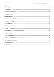
W.) Packaged Unpackaged TFT Color LCD 43cm(17.0") 0.264mm(H) x 0.264mm(V) 140˚ (H) 120˚ (V) 16 ms Analog Only H/V TTL Separate and Composite Sync. 30kHz - 80kHz 56-75Hz Over 16.2 million Colors 135MHz 1280 x 1024 VESA DDC2BTM Resolution Plug & Play Power Consumption Driving system Size Pixel pitch Viewable angle Response time (typ.) Video Sync. Type H-Frequency V-Frequency ON Mode Power Saving Maximum Screen Size Power Source Environmental Considerations Weight (N. MONITOR SPECIFICATIONS LCD Panel Input Display Colors Dot Clock Max. DELL E173FP Service Manual 1.
W.) Packaged Unpackaged TFT Color LCD 43cm(17.0") 0.264mm(H) x 0.264mm(V) 140˚ (H) 120˚ (V) 16 ms Analog Only H/V TTL Separate and Composite Sync. 30kHz - 80kHz 56-75Hz Over 16.2 million Colors 135MHz 1280 x 1024 VESA DDC2BTM Resolution Plug & Play Power Consumption Driving system Size Pixel pitch Viewable angle Response time (typ.) Video Sync. Type H-Frequency V-Frequency ON Mode Power Saving Maximum Screen Size Power Source Environmental Considerations Weight (N. MONITOR SPECIFICATIONS LCD Panel Input Display Colors Dot Clock Max. DELL E173FP Service Manual 1.
Service Manual
Page 5
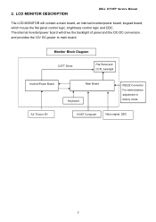
and provides the 12V DC-power to main board. Flat Panel and CCFL backlight Inverter/Power Board AC Power IN Main Board Keyboard RS232 Connector For white balance adjustment in factory mode HOST Computer Video signal, DDC 5 LCD MONITOR DESCRIPTION DELL E173FP Service Manual The LCD MONITOR will drive the backlight of panel and the DC-DC conversion. Monitor Block Diagram CCFT Driver. 2. The internal Inverter/power board will contain a main board, an internal inverter/power board, keypad board, which house the flat panel control logic, brightness control logic and DDC.
and provides the 12V DC-power to main board. Flat Panel and CCFL backlight Inverter/Power Board AC Power IN Main Board Keyboard RS232 Connector For white balance adjustment in factory mode HOST Computer Video signal, DDC 5 LCD MONITOR DESCRIPTION DELL E173FP Service Manual The LCD MONITOR will drive the backlight of panel and the DC-DC conversion. Monitor Block Diagram CCFT Driver. 2. The internal Inverter/power board will contain a main board, an internal inverter/power board, keypad board, which house the flat panel control logic, brightness control logic and DDC.

Service Manual
Page 6
... LED turns blank. Press to the video card. - Power On mode. Power Saving mode. The other control buttons are located at front panel of the monitor. Press again to automatically set the H Position, V Position, Clock and Phase. - Power Indicator: Green - Blank -Power Off Mode. Buttons for the OSD menu (On-Screen... your personal preferences. - Auto Adjust Key: The Auto Adjust Key is used to restore normal status. - By changing these settings, the picture can be connected. - DELL E173FP Service Manual 3.
... LED turns blank. Press to the video card. - Power On mode. Power Saving mode. The other control buttons are located at front panel of the monitor. Press again to automatically set the H Position, V Position, Clock and Phase. - Power Indicator: Green - Blank -Power Off Mode. Buttons for the OSD menu (On-Screen... your personal preferences. - Auto Adjust Key: The Auto Adjust Key is used to restore normal status. - By changing these settings, the picture can be connected. - DELL E173FP Service Manual 3.

Service Manual
Page 7
... another icon (e.g. The main menu appears on the screen with icons for the selected function. Press the SELECT/MENU button to activate the OSD menu. DELL E173FP Service Manual 3.3 ADJUSTING THE PICTURE To set the OSD menu, perform the following steps: Briefly press the SELCT / MENU button to exit the sub-menu when "Exit...
... another icon (e.g. The main menu appears on the screen with icons for the selected function. Press the SELECT/MENU button to activate the OSD menu. DELL E173FP Service Manual 3.3 ADJUSTING THE PICTURE To set the OSD menu, perform the following steps: Briefly press the SELCT / MENU button to exit the sub-menu when "Exit...

Service Manual
Page 8
...it 's 6500K; Setting display of the OSD menu Calling the OSD Set up setting window Horizontal Setting the horizontal position of the LCD display, it 's 9300K; Normal preset = Original colour of the OSD menu Position With this function you move the picture up ...Auto Adjust Auto adjust will produce best image automatically, The information of the LCD display, it's 5700K; Vertical Setting the vertical position of the basic colours (red, green, blue) as required. DELL E173FP Service Manual Adjusting size and position Calling the Positioning setting window H-Position Adjusting the ...
...it 's 6500K; Setting display of the OSD menu Calling the OSD Set up setting window Horizontal Setting the horizontal position of the LCD display, it 's 9300K; Normal preset = Original colour of the OSD menu Position With this function you move the picture up ...Auto Adjust Auto adjust will produce best image automatically, The information of the LCD display, it's 5700K; Vertical Setting the vertical position of the basic colours (red, green, blue) as required. DELL E173FP Service Manual Adjusting size and position Calling the Positioning setting window H-Position Adjusting the ...

Service Manual
Page 9
... settings without a setting being made, the OSD menu is automatically faded out. With this function you select a value from 0 to 60 seconds. OSD Hold Time DELL E173FP Service Manual Setting the display duration of the OSD menu With this function you select Yes to lock OSD, NO to unlock it. If the set time...
... settings without a setting being made, the OSD menu is automatically faded out. With this function you select a value from 0 to 60 seconds. OSD Hold Time DELL E173FP Service Manual Setting the display duration of the OSD menu With this function you select Yes to lock OSD, NO to unlock it. If the set time...

Service Manual
Page 10
...1024 1280 x 1024 For ergonomic reasons, a screen resolution of 60 Hz. 10 Input/Output Specification 4.1 Input Signal Connector 4.1.1 Analog D-SUB Connector DELL E173FP Service Manual 10 5 9 4 8 3 7 2 6 1 17 16 15 14 13 12 11 Pin Meaning Pin 1 Video input red 9 2 Video input green 10 3 Video input blue 11 4 Ground ... Sync V. 4. Sync DDC Clock 4.2 Factory Preset Display Modes The following are the most frequently used (active matrix) an LCD monitor provides a totally flicker-free picture even with a refresh rate of 1280 x 1024 pixels is recommended.
...1024 1280 x 1024 For ergonomic reasons, a screen resolution of 60 Hz. 10 Input/Output Specification 4.1 Input Signal Connector 4.1.1 Analog D-SUB Connector DELL E173FP Service Manual 10 5 9 4 8 3 7 2 6 1 17 16 15 14 13 12 11 Pin Meaning Pin 1 Video input red 9 2 Video input green 10 3 Video input blue 11 4 Ground ... Sync V. 4. Sync DDC Clock 4.2 Factory Preset Display Modes The following are the most frequently used (active matrix) an LCD monitor provides a totally flicker-free picture even with a refresh rate of 1280 x 1024 pixels is recommended.

Service Manual
Page 12
DELL E173FP Service Manual 4.4.3 Optical Characteristics The optical characteristics are measured under stable conditions at 25℃ (Room Temperature): 4.4.4 Parameter guide line for CCFL Inverter 12
DELL E173FP Service Manual 4.4.3 Optical Characteristics The optical characteristics are measured under stable conditions at 25℃ (Room Temperature): 4.4.4 Parameter guide line for CCFL Inverter 12

Service Manual
Page 15
DELL E173FP Service Manual 1) MCU Initializes. 2) Is the EEprom blank? 3) Program the EEprom by default values. 4) Get the PWM value of back light. 12) Check the analog port, are ... all global flags. 7) Are the AUTO and SELECT keys pressed? 8) Enter factory mode. 9) Save the power key status into standby mode after the message disappears. 17) Program the scalar to be able to green color. Scalar initializes. 10) In standby mode? 11) Update the lifetime of brightness from analog port? 16...
DELL E173FP Service Manual 1) MCU Initializes. 2) Is the EEprom blank? 3) Program the EEprom by default values. 4) Get the PWM value of back light. 12) Check the analog port, are ... all global flags. 7) Are the AUTO and SELECT keys pressed? 8) Enter factory mode. 9) Save the power key status into standby mode after the message disappears. 17) Program the scalar to be able to green color. Scalar initializes. 10) In standby mode? 11) Update the lifetime of brightness from analog port? 16...

Service Manual
Page 17
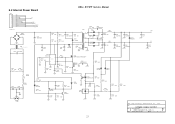
...V R8 CCFL R9 M4 10 Vrms METER V R12 CCFL R10 CCFL R11 M5 10 Vrms METER V R13 M6 10 Vrms METER V CON205 1 2 CON206 1 2 CON207 1 2 CON208 1 2 DELL E173FP Service Manual Model name : PWPC1742LGD1 PCB NO.715L1283-1 CN102 1 2 3 4 5 6 7 8 9 10 11 12 GND ON/OFF DIM 12V 5V GND GND L N CN901 AC IN M2 R2 5 V...need to 5V) , then check M3 / M4/M5/M6 Vrms . 2. Specification : M1 = 12V +- 0.5V , M2 = 5V +- 0.25V 1. M3 / M4/M5/M6= 55KHz +- 5 KHz 17 M3 / M4/M5/M6 = 6.5 +- 5 mV @ DIM= 5V M3 / M4 /M5/M6= 3.0 +- 5 mV @ DIM= 0V 2. Adjust VR1 ( Set Vdim voltage from 0V to use ...
...V R8 CCFL R9 M4 10 Vrms METER V R12 CCFL R10 CCFL R11 M5 10 Vrms METER V R13 M6 10 Vrms METER V CON205 1 2 CON206 1 2 CON207 1 2 CON208 1 2 DELL E173FP Service Manual Model name : PWPC1742LGD1 PCB NO.715L1283-1 CN102 1 2 3 4 5 6 7 8 9 10 11 12 GND ON/OFF DIM 12V 5V GND GND L N CN901 AC IN M2 R2 5 V...need to 5V) , then check M3 / M4/M5/M6 Vrms . 2. Specification : M1 = 12V +- 0.5V , M2 = 5V +- 0.25V 1. M3 / M4/M5/M6= 55KHz +- 5 KHz 17 M3 / M4/M5/M6 = 6.5 +- 5 mV @ DIM= 5V M3 / M4 /M5/M6= 3.0 +- 5 mV @ DIM= 0V 2. Adjust VR1 ( Set Vdim voltage from 0V to use ...
Service Manual
Page 19
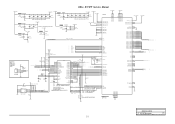
DELL E173FP Service Manual +3.3V_VDD 58.27m A +1.8V_VDD 3.3V_DVDD 139m A 1.8V_DVDD 3.3V_PVDD 3.3V_AVDD L101 120 OHM C122 + 22uF/16V GND ...DDC_SCL 97 DDC_SDA 98 GPIO10/IRQn DDC_SCL DDC_SDA 11 13 14 15 P3.0/RXD P3.1/TXD P3.2/INT0# 16 P3.3/INT1# 17 P3.4/T0 P3.5/T1 20 21 XTAL2 XTAL1 35 44 EA#/VPP VCC 22 VSS 36 AD7/P0.7 AD6/P0.6 AD5/.../R3 CH2P_LV_E/R4 CH2N_LV_E/R5 CH1P_LV_E/R6 CH1N_LV_E/R7 CH0P_LV_E/G0 6 7 8 9 10 11 12 13 14 CH0N_LV_E/G1 17 CH3P_LV_O/G2 18 CH3N_LV_O/G3 CLKP_LV_O/G4 CLKN_LV_O/G5 19 20 21 CH2P_LV_O/G6 22 CH2N_LV_O/G7 CH1P_LV_O/B0 CH1N_LV_O/B1 CH0P_LV_O/...
DELL E173FP Service Manual +3.3V_VDD 58.27m A +1.8V_VDD 3.3V_DVDD 139m A 1.8V_DVDD 3.3V_PVDD 3.3V_AVDD L101 120 OHM C122 + 22uF/16V GND ...DDC_SCL 97 DDC_SDA 98 GPIO10/IRQn DDC_SCL DDC_SDA 11 13 14 15 P3.0/RXD P3.1/TXD P3.2/INT0# 16 P3.3/INT1# 17 P3.4/T0 P3.5/T1 20 21 XTAL2 XTAL1 35 44 EA#/VPP VCC 22 VSS 36 AD7/P0.7 AD6/P0.6 AD5/.../R3 CH2P_LV_E/R4 CH2N_LV_E/R5 CH1P_LV_E/R6 CH1N_LV_E/R7 CH0P_LV_E/G0 6 7 8 9 10 11 12 13 14 CH0N_LV_E/G1 17 CH3P_LV_O/G2 18 CH3N_LV_O/G3 CLKP_LV_O/G4 CLKN_LV_O/G5 19 20 21 CH2P_LV_O/G6 22 CH2N_LV_O/G7 CH1P_LV_O/B0 CH1N_LV_O/B1 CH0P_LV_O/...

Service Manual
Page 20
DELL E173FP Service Manual +5V +5V +5V 3 5 6 7 8 2 KEY _MENU 2 KEY _RIGHT 2 KEY _LEFT 2 KEY _ONOFF KEY _MENU KEY _RIGHT KEY _LEFT KEY _ONOFF 4 3 2 1 RP103 4.7K 1/16W 2 LED_O R155 LED_O 1 4....
DELL E173FP Service Manual +5V +5V +5V 3 5 6 7 8 2 KEY _MENU 2 KEY _RIGHT 2 KEY _LEFT 2 KEY _ONOFF KEY _MENU KEY _RIGHT KEY _LEFT KEY _ONOFF 4 3 2 1 RP103 4.7K 1/16W 2 LED_O R155 LED_O 1 4....

Service Manual
Page 21
CN103 1 2 3 4 5 6 7 8 9 10 11 12 13 14 15 16 17 18 19 20 21 22 23 24 RXO0+ RXO1+ RXO2+ RXOC+ RXO3+ RXE0+ RXE1+ RXE2+ RXEC+ RXE3+ LVDS_O1 LVDS_O3 LVDS_O5 LVDS_O7 LVDS_O9 LVDS_E1 LVDS_E3 LVDS_E5 ... Sheet 4 of 5 21 2 LVDS_O[0..9] 2 LVDS_E[0..9] LVDS_O0 LVDS_O1 LVDS_O2 LVDS_O3 LVDS_O4 LVDS_O5 LVDS_O6 LVDS_O7 LVDS_O8 LVDS_O9 LVDS_E0 LVDS_E1 LVDS_E2 LVDS_E3 LVDS_E4 LVDS_E5 LVDS_E6 LVDS_E7 LVDS_E8 LVDS_E9 DELL E173FP Service Manual LVDS_O0 LVDS_O2 LVDS_O4 LVDS_O6 LVDS_O8 LVDS_E0 LVDS_E2 LVDS_E4 LVDS_E6 LVDS_E8 RXO0RXO1RXO2RXOCRXO3RXE0RXE1RXE2RXECRXE3-
CN103 1 2 3 4 5 6 7 8 9 10 11 12 13 14 15 16 17 18 19 20 21 22 23 24 RXO0+ RXO1+ RXO2+ RXOC+ RXO3+ RXE0+ RXE1+ RXE2+ RXEC+ RXE3+ LVDS_O1 LVDS_O3 LVDS_O5 LVDS_O7 LVDS_O9 LVDS_E1 LVDS_E3 LVDS_E5 ... Sheet 4 of 5 21 2 LVDS_O[0..9] 2 LVDS_E[0..9] LVDS_O0 LVDS_O1 LVDS_O2 LVDS_O3 LVDS_O4 LVDS_O5 LVDS_O6 LVDS_O7 LVDS_O8 LVDS_O9 LVDS_E0 LVDS_E1 LVDS_E2 LVDS_E3 LVDS_E4 LVDS_E5 LVDS_E6 LVDS_E7 LVDS_E8 LVDS_E9 DELL E173FP Service Manual LVDS_O0 LVDS_O2 LVDS_O4 LVDS_O6 LVDS_O8 LVDS_E0 LVDS_E2 LVDS_E4 LVDS_E6 LVDS_E8 RXO0RXO1RXO2RXOCRXO3RXE0RXE1RXE2RXECRXE3-
Service Manual
Page 23
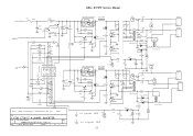
... 12V DIM GND ON/OFF GND 33A8009-12G-H 5V 12V DIM ON/OFF GND +4 DB901 2KBP06M 1 3 + C904 120uF/400V 2- 2 3 L902 73L-174-26-T 1 4 C907 0.1uF DELL E173FP Service Manual R906 1M 1/4W R907 1M 1/4W T901 1 O 9 R904 1M 1/4W C905 R903 0.0015uF/2KV 100K 2W R905 1M 1/4W D901 O 7,8 UF4007 3 7,8 5 + D902 C906 PS102R 22uF...
... 12V DIM GND ON/OFF GND 33A8009-12G-H 5V 12V DIM ON/OFF GND +4 DB901 2KBP06M 1 3 + C904 120uF/400V 2- 2 3 L902 73L-174-26-T 1 4 C907 0.1uF DELL E173FP Service Manual R906 1M 1/4W R907 1M 1/4W T901 1 O 9 R904 1M 1/4W C905 R903 0.0015uF/2KV 100K 2W R905 1M 1/4W D901 O 7,8 UF4007 3 7,8 5 + D902 C906 PS102R 22uF...
Service Manual
Page 24
...7 80AL15T-7-YS R233 1K D206 RLS4148 D210 RLS4148 1 TP6 1 HVL 1 L204 4 2 3 0.1U/25V AOC (Top Victory) Electronics Co., Ltd. Title 2. FOR 17"&15" 4 LAMPS INVERTER Size Document Number PWPC1742LGD1(715L-1283-1) Date: Tuesday, March 16, 2004 Sheet 2 of Rev A 2 C222 is power GND 0.47U/25V is signal... 510 C225 OPEN 73L-174-30-YS CON201 1 2 33L8021-2D CON203 1 2 33L8021-2D CON202 1 2 33L8021-2D CON204 1 2 33L8021-2D DELL E173FP Service Manual +12V NO/OFF DIM F201 4A/63V L205 JUMP C202 Q201 0.1U/25V DTC144WKA Q202 DTA144WKA C204 0.1U/25V R202 5.1K R207 OPEN C207 4.7U...
...7 80AL15T-7-YS R233 1K D206 RLS4148 D210 RLS4148 1 TP6 1 HVL 1 L204 4 2 3 0.1U/25V AOC (Top Victory) Electronics Co., Ltd. Title 2. FOR 17"&15" 4 LAMPS INVERTER Size Document Number PWPC1742LGD1(715L-1283-1) Date: Tuesday, March 16, 2004 Sheet 2 of Rev A 2 C222 is power GND 0.47U/25V is signal... 510 C225 OPEN 73L-174-30-YS CON201 1 2 33L8021-2D CON203 1 2 33L8021-2D CON202 1 2 33L8021-2D CON204 1 2 33L8021-2D DELL E173FP Service Manual +12V NO/OFF DIM F201 4A/63V L205 JUMP C202 Q201 0.1U/25V DTC144WKA Q202 DTA144WKA C204 0.1U/25V R202 5.1K R207 OPEN C207 4.7U...

Service Manual
Page 28
Maintainability 8.1 Equipments and Tools Requirement ¾ Voltage meter. ¾ Oscilloscope. ¾ Pattern Generator. ¾ DDC Tool with a IBM Compatible Computer. ¾ Alignment Tool. ¾ LCD Color Analyzer. ¾ Service Manual. ¾ User Manual. 28 7.3 Keypad Board DELL E173FP Service Manual 8.
Maintainability 8.1 Equipments and Tools Requirement ¾ Voltage meter. ¾ Oscilloscope. ¾ Pattern Generator. ¾ DDC Tool with a IBM Compatible Computer. ¾ Alignment Tool. ¾ LCD Color Analyzer. ¾ Service Manual. ¾ User Manual. 28 7.3 Keypad Board DELL E173FP Service Manual 8.

Service Manual
Page 29
... status. If Replace "MAIN-BOARD", Please re-do "DDC-content" programmed & "WHITE-Balance". 2. Check Correspondent component short/open Protection Diode and NG Signal cable bad? DELL E173FP Service Manual No DC Level Check Power board, is disconnected? Measured U105 pin 2= 3.3V? Check Power switch is show Block WRGB color bars? Check U105 pin3=5V...
... status. If Replace "MAIN-BOARD", Please re-do "DDC-content" programmed & "WHITE-Balance". 2. Check Correspondent component short/open Protection Diode and NG Signal cable bad? DELL E173FP Service Manual No DC Level Check Power board, is disconnected? Measured U105 pin 2= 3.3V? Check Power switch is show Block WRGB color bars? Check U105 pin3=5V...


