Service Manual
Page 47
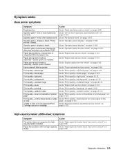
...feeder input tray service check" on page 2-113. Go to "No buttons work . Go to "Paper feed service check" on page 2-108. Go to "Paper feed service check" on page 2-96. High-capacity feeder (2000-sheet) symptoms Symptom Action The printer does not recognize the ...highcapacity feeder installed. Symptom tables Base printer symptoms Symptom Action Dead machine Operator panel-one or more operator panel buttons fail" on page 2-107. Go...
...feeder input tray service check" on page 2-113. Go to "No buttons work . Go to "Paper feed service check" on page 2-108. Go to "Paper feed service check" on page 2-96. High-capacity feeder (2000-sheet) symptoms Symptom Action The printer does not recognize the ...highcapacity feeder installed. Symptom tables Base printer symptoms Symptom Action Dead machine Operator panel-one or more operator panel buttons fail" on page 2-107. Go...

Service Manual
Page 49
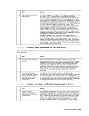
...on page 2-124. Go to "StapleSmart finisher service check" on page 2-124. Paper feeds into finisher option. Go to the output tray. The stapler does not staple. Stapled sheets are not transported to "StapleSmart finisher service check" on page 2-124. Go to "StapleSmart.... Paper feeds into finisher option output tray. Paper is transported into the output tray but is not stapled and paper does not align with the right side. StapleSmart finisher Symptom Action Finisher does not staple. Printer does not recognize StapleSmart Finisher Option as being installed. ...
...on page 2-124. Go to "StapleSmart finisher service check" on page 2-124. Paper feeds into finisher option. Go to the output tray. The stapler does not staple. Stapled sheets are not transported to "StapleSmart finisher service check" on page 2-124. Go to "StapleSmart.... Paper feeds into finisher option output tray. Paper is transported into the output tray but is not stapled and paper does not align with the right side. StapleSmart finisher Symptom Action Finisher does not staple. Printer does not recognize StapleSmart Finisher Option as being installed. ...

Service Manual
Page 85
... available. User status message Check Env Feeder Connection Check Tray x Connection Check Duplex Connection Explanation Check envelope feeder connection. The duplex rear door is recognized, the printer automatically clears the error and continues. Link messages are active when the printer is advised to turn the printer off , remove the option, and call for instance to...
... available. User status message Check Env Feeder Connection Check Tray x Connection Check Duplex Connection Explanation Check envelope feeder connection. The duplex rear door is recognized, the printer automatically clears the error and continues. Link messages are active when the printer is advised to turn the printer off , remove the option, and call for instance to...

Service Manual
Page 126
...and continue with this does not fix the problem, replace the envelope system board. 2-84 Service Manual Disconnect the autoconnect cable at J1-7, tray 1 is the only tray that is not present at J1 on the envelope system board and measure the following voltages: • J1-3 measures +5 V dc ...when the flag is functioning properly. If this service check, otherwise verify the interconnect card is moved in and out of the printer. If +24 V dc is recognized. Perform an envelope feeder sensor test to damage the flag. Be careful not to check both the sensor and sensor flag. ...
...and continue with this does not fix the problem, replace the envelope system board. 2-84 Service Manual Disconnect the autoconnect cable at J1-7, tray 1 is the only tray that is not present at J1 on the envelope system board and measure the following voltages: • J1-3 measures +5 V dc ...when the flag is functioning properly. If this service check, otherwise verify the interconnect card is moved in and out of the printer. If +24 V dc is recognized. Perform an envelope feeder sensor test to damage the flag. Be careful not to check both the sensor and sensor flag. ...

Service Manual
Page 138
...jumper from the AC wiring harness to the frame of the LVPS. 2-96 Service Manual If defective, replace the cord. The base printer does not recognize that the high-capacity input tray is not pushed down into the frame assembly or damaged. Be sure the high-capacity feeder input... tray autoconnect is properly connected to make sure it is mounted correctly and is installed FRU 1 high-capacity feeder autoconnect mechanical check 2 Base printer or option ...
...jumper from the AC wiring harness to the frame of the LVPS. 2-96 Service Manual If defective, replace the cord. The base printer does not recognize that the high-capacity input tray is not pushed down into the frame assembly or damaged. Be sure the high-capacity feeder input... tray autoconnect is properly connected to make sure it is mounted correctly and is installed FRU 1 high-capacity feeder autoconnect mechanical check 2 Base printer or option ...
Service Manual
Page 139
...board. If the test fails, check the sensor for correct installation and the flag for proper operation by running the appropriate Tray Sensor Test from the printer and check the pass thru sensor and flag for proper operation. Also check the sensor cable to make sure it is full...-4(red). Check the drive roll assembly and skewed backup roller for the paper tray where the error occurs. If no shorts are correct, check the stepper motor for shorts from the motor housing to be recognized. Repair or replace parts as necessary. control board If incorrect, check the ...
...board. If the test fails, check the sensor for correct installation and the flag for proper operation by running the appropriate Tray Sensor Test from the printer and check the pass thru sensor and flag for proper operation. Also check the sensor cable to make sure it is full...-4(red). Check the drive roll assembly and skewed backup roller for the paper tray where the error occurs. If no shorts are correct, check the stepper motor for shorts from the motor housing to be recognized. Repair or replace parts as necessary. control board If incorrect, check the ...

Service Manual
Page 141
... direction only FRU 1 DC drive motor assembly high-capacity feeder system board Action Check the voltages at J1 on the high-capacity system board. the printer recognizes that the option is found , measure the resistance between the following pins on the motor cable connector: Pins 1 (brown) and pin 2 (Yellow) The resistance measures...
... direction only FRU 1 DC drive motor assembly high-capacity feeder system board Action Check the voltages at J1 on the high-capacity system board. the printer recognizes that the option is found , measure the resistance between the following pins on the motor cable connector: Pins 1 (brown) and pin 2 (Yellow) The resistance measures...

Service Manual
Page 146
... check the pass thru sensor and flag for signs of cuts, pinched wiring, or other damage especially at the tray x system board. Repair or replace parts as necessary. system board) Printer does not recognize Tray x is 2 Paper out sensor (on option mounted on the rollers. 24x.xx Paper Jam displays, paper jammed over the...
... check the pass thru sensor and flag for signs of cuts, pinched wiring, or other damage especially at the tray x system board. Repair or replace parts as necessary. system board) Printer does not recognize Tray x is 2 Paper out sensor (on option mounted on the rollers. 24x.xx Paper Jam displays, paper jammed over the...

Service Manual
Page 157
It should measure approximately 0 ohms. Diagnostic information 2-115 unable to clear Tray 1 Missing message FRU 1 Tray 1 Action Check Tray 1 for correct installation of the cable at J26 on the system board and ground. If installed correctly, go to step 3.... fingers. If no problem is found , go to step 2. Check the continuity between J26-2 on the system board. If incorrectly installed, install and recheck the printer. Check for anything that would prevent the autosize fingers from activating the paper activate springs and ITC switches. 2 W S 1 W S 0 W S LGL A4 LTREXBE5C ...
It should measure approximately 0 ohms. Diagnostic information 2-115 unable to clear Tray 1 Missing message FRU 1 Tray 1 Action Check Tray 1 for correct installation of the cable at J26 on the system board and ground. If installed correctly, go to step 3.... fingers. If no problem is found , go to step 2. Check the continuity between J26-2 on the system board. If incorrectly installed, install and recheck the printer. Check for anything that would prevent the autosize fingers from activating the paper activate springs and ITC switches. 2 W S 1 W S 0 W S LGL A4 LTREXBE5C ...

Service Manual
Page 158
..., go to step 3. Set the tray for damage or broken parts. If it is not displayed, go to step 5. If correct, replace the ITC assembly. make sure the parts operate correctly. Check continuity of the autocomp cable. Replace the spring if damaged. The printer does not recognize the paper size selected FRU 1 Back...
..., go to step 3. Set the tray for damage or broken parts. If it is not displayed, go to step 5. If correct, replace the ITC assembly. make sure the parts operate correctly. Check continuity of the autocomp cable. Replace the spring if damaged. The printer does not recognize the paper size selected FRU 1 Back...

Service Manual
Page 204
Autoconnect system, paper tray options, envelope feeder-electrical Autoconnect cabling and connectors The printer options make electrical connection automatically, requiring no longer recognizes the option and deletes associated messages. Duplex Option The duplex option interface is provided from the base printer for duplex electronics. Duplex chassis grounding is a six pin autoconnector that have a system board...
Autoconnect system, paper tray options, envelope feeder-electrical Autoconnect cabling and connectors The printer options make electrical connection automatically, requiring no longer recognizes the option and deletes associated messages. Duplex Option The duplex option interface is provided from the base printer for duplex electronics. Duplex chassis grounding is a six pin autoconnector that have a system board...

Service Manual
Page 389
...recognizes any options you have purchased in the following order: CAUTION: If you are using a 2000-sheet drawer, a duplex unit and an input option, or more than one input option. Decals Appendix A-Options and features A-1 Installing input options Order of a tray and a support unit. You must use either a printer stand or printer...you purchased an MFP that is available on installing a printer stand, printer base, or 2000-sheet drawer, see the instructions included with the option. For information on the Dell Web site at www.dell.com. Remove all packing material and tape from the support...
...recognizes any options you have purchased in the following order: CAUTION: If you are using a 2000-sheet drawer, a duplex unit and an input option, or more than one input option. Decals Appendix A-Options and features A-1 Installing input options Order of a tray and a support unit. You must use either a printer stand or printer...you purchased an MFP that is available on installing a printer stand, printer base, or 2000-sheet drawer, see the instructions included with the option. For information on the Dell Web site at www.dell.com. Remove all packing material and tape from the support...


