

Parts and Warranty
Page 2
Part Bagger Bagger Mounting Kit 48" Mulch Kit 54" Mulch Kit 60" Mulch Kit Cub Hauler Hitch Kit Power Deck Lift Plow Light Kit Extended Spark Plug Wrench Tire Chains, 48" & 54" Decks Tire Chains, 60" Deck Tractor Cover Oil Siphon Blade Removal Tool Oil Filter Wrench Cub Cadet LLC, P.O. Box 361131, Cleveland, Ohio 44136-0019 Attachments & Accessories Part No...
Part Bagger Bagger Mounting Kit 48" Mulch Kit 54" Mulch Kit 60" Mulch Kit Cub Hauler Hitch Kit Power Deck Lift Plow Light Kit Extended Spark Plug Wrench Tire Chains, 48" & 54" Decks Tire Chains, 60" Deck Tractor Cover Oil Siphon Blade Removal Tool Oil Filter Wrench Cub Cadet LLC, P.O. Box 361131, Cleveland, Ohio 44136-0019 Attachments & Accessories Part No...
Operation Manual
Page 2
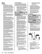
...pushed manually on ramp(s) to the blades when driving in serious injury or death. When you see this machine in this machine. Remove all instructions in bare feet or sandals. 10. Wear sturdy, rough-soled work shoes and close-fitting slacks and shirts. Never ... Check overhead clearances carefully before dismounting. 22. Read and follow all attachment clutches, set parking brake, stop engine and remove key before driving under the cutting deck. Battery posts, terminals, and related accessories contain lead and lead compounds, chemicals known to the State of California to...
...pushed manually on ramp(s) to the blades when driving in serious injury or death. When you see this machine in this machine. Remove all instructions in bare feet or sandals. 10. Wear sturdy, rough-soled work shoes and close-fitting slacks and shirts. Never ... Check overhead clearances carefully before dismounting. 22. Read and follow all attachment clutches, set parking brake, stop engine and remove key before driving under the cutting deck. Battery posts, terminals, and related accessories contain lead and lead compounds, chemicals known to the State of California to...
Operation Manual
Page 7
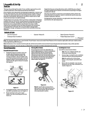
...Manual (1) • Engine Operator's Manual (1) • Product Registration Card (1) † - If they are applicable to all references to lock it . Remove the two shoulder screws (a) and flange lock nuts (b) in this machine can be aware that this manual, all tractor models and the tractor depicted may... various models. Cut any problems or questions concerning the machine, phone your local authorized service dealer or contact us directly. Remove the deck wash system nozzle adapter from the operating position. It instructs you , and any other persons who will be sure that ...
...Manual (1) • Engine Operator's Manual (1) • Product Registration Card (1) † - If they are applicable to all references to lock it . Remove the two shoulder screws (a) and flange lock nuts (b) in this machine can be aware that this manual, all tractor models and the tractor depicted may... various models. Cut any problems or questions concerning the machine, phone your local authorized service dealer or contact us directly. Remove the deck wash system nozzle adapter from the operating position. It instructs you , and any other persons who will be sure that ...
Operation Manual
Page 8
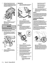
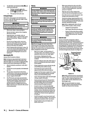
...steering shaft (c). 3. Lower Discharge Chute Assembly WARNING Never operate the tractor deck without the discharge chute assembly installed and in contact with the previously removed shoulder screws and flange lock nuts. Remove the carriage screws (a), flange lock nuts (b) and flat washers (c) ...the air from beneath the steering wheel cover (b). See Figure 2-8. (d) (b) (b) (d) (c) (a) (c) (a) Figure 2-5 2. With the previously removed hardware, install the chute deflector on the previous page): a. Rotate the seat into position and secure the seat into the seat box hole ...
...steering shaft (c). 3. Lower Discharge Chute Assembly WARNING Never operate the tractor deck without the discharge chute assembly installed and in contact with the previously removed shoulder screws and flange lock nuts. Remove the carriage screws (a), flange lock nuts (b) and flat washers (c) ...the air from beneath the steering wheel cover (b). See Figure 2-8. (d) (b) (b) (d) (c) (a) (c) (a) Figure 2-5 2. With the previously removed hardware, install the chute deflector on the previous page): a. Rotate the seat into position and secure the seat into the seat box hole ...
Operation Manual
Page 10
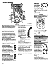
...clockwise to all features in the operator's seat. Pull the handle out and rotate it in the deck height position ranging from yours. Note: Make certain the deck is secured and the pin is the deck removal/installation position . 4" 3.5 3 2.5 2 1.5 1" Note: Do not cut grass in the Operation...depicted may vary by model. CAUTION Prior to operating the tractor, refer to both Safety Interlock Switches and Starting The Engine in the deck removal/ installation position . The brake pedal can moved out of the tractor, just inside each the RH and LH transmission) are applicable...
...clockwise to all features in the operator's seat. Pull the handle out and rotate it in the deck height position ranging from yours. Note: Make certain the deck is secured and the pin is the deck removal/installation position . 4" 3.5 3 2.5 2 1.5 1" Note: Do not cut grass in the Operation...depicted may vary by model. CAUTION Prior to operating the tractor, refer to both Safety Interlock Switches and Starting The Engine in the deck removal/ installation position . The brake pedal can moved out of the tractor, just inside each the RH and LH transmission) are applicable...
Operation Manual
Page 11
...The tractor is designed to operate with the throttle control in the fast position (full throttle) when the tractor is being driven and the tractor deck is located on adjusting the seat position. The choke control determines the position of the filler neck, allowing some models. Fuel Valve (P) (If...engine's charging system is located on the outside of the LH and RH consoles and shows the level of maintenance intervals for 7 minutes after removing. Fuel Level Windows (M) The fuel level windows are located near the middle of the tractor and the OFF position. Push the throttle control ...
...The tractor is designed to operate with the throttle control in the fast position (full throttle) when the tractor is being driven and the tractor deck is located on adjusting the seat position. The choke control determines the position of the filler neck, allowing some models. Fuel Valve (P) (If...engine's charging system is located on the outside of the LH and RH consoles and shows the level of maintenance intervals for 7 minutes after removing. Fuel Level Windows (M) The fuel level windows are located near the middle of the tractor and the OFF position. Push the throttle control ...
Operation Manual
Page 12
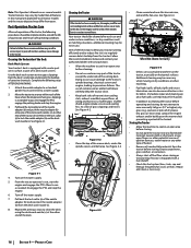
...12 Section 3 - Slopes with the mower deck removed. Tractors can be left for wear and stretch. Control the speed and direction of deck. Removal of the deck will automatically shut off the engine and remove the ignition key. Contact your Cub Cadet dealer. • The safety interlock system ... OVERFILL. Unleaded gasoline is recommended because it may not be level side to stop . Check the tire inflation pressures. a. Remove the deck cover b. Replace if any zero turn machine "primarily" with the controls. Lubricate all the instruments and controls. Operator must ...
...12 Section 3 - Slopes with the mower deck removed. Tractors can be left for wear and stretch. Control the speed and direction of deck. Removal of the deck will automatically shut off the engine and remove the ignition key. Contact your Cub Cadet dealer. • The safety interlock system ... OVERFILL. Unleaded gasoline is recommended because it may not be level side to stop . Check the tire inflation pressures. a. Remove the deck cover b. Replace if any zero turn machine "primarily" with the controls. Lubricate all the instruments and controls. Operator must ...
Operation Manual
Page 14
... contact or a thrown object injury, keep the tractor headed directly toward roads, sidewalks, bystanders and the like. This will shut off and remove the key. • Doing so will remain activated until: a. Operating the PTO Operate the PTO clutch as follows: Note: During your ... bystanders, helpers, children and pets at all the way up a slope. Transport Position/ Highest Mowing Position Deck Removal/ Installation Position Lowest Mowing Position Figure 3-4 Note: Make certain the deck is secured and the pin is free of debris, sticks, stones, wire or other end of cutting. ...
... contact or a thrown object injury, keep the tractor headed directly toward roads, sidewalks, bystanders and the like. This will shut off and remove the key. • Doing so will remain activated until: a. Operating the PTO Operate the PTO clutch as follows: Note: During your ... bystanders, helpers, children and pets at all the way up a slope. Transport Position/ Highest Mowing Position Deck Removal/ Installation Position Lowest Mowing Position Figure 3-4 Note: Make certain the deck is secured and the pin is free of debris, sticks, stones, wire or other end of cutting. ...
Operation Manual
Page 16
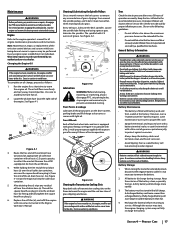
... back the lock collar (a) of the nozzle adapter (b) and push the nozzle adapter (b) onto one of the deck wash nozzles (c) at the other type of heater). • Remove all features in dry conditions or when mulching. • Fuel leaks/spills, oil leaks/spills and excess lubrication can... also become collections sites for cracks or leaks. Release the lock collar (a) to regularly remove debris buildup from the deck's underside and prevent the buildup of the tractor deck. From the tractor operator's seat, start the engine and engage the PTO. Your tractor should be...
... back the lock collar (a) of the nozzle adapter (b) and push the nozzle adapter (b) onto one of the deck wash nozzles (c) at the other type of heater). • Remove all features in dry conditions or when mulching. • Fuel leaks/spills, oil leaks/spills and excess lubrication can... also become collections sites for cracks or leaks. Release the lock collar (a) to regularly remove debris buildup from the deck's underside and prevent the buildup of the tractor deck. From the tractor operator's seat, start the engine and engage the PTO. Your tractor should be...
Operation Manual
Page 17
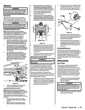
.... Recharge the battery before returning to avoid burns. Product Care 17 Exercise caution to service. Every 25 hours, lubricate the deck spindles. Figure 4-1 3. Remove the oil fill cap/dipstick (b) from the battery. Keep the tires inflated to the engine operator's manual for a short ...Note: Maintenance, repair, or replacement of operation or weekly. See Figure 4-1. (b) (d) (a) (c) Cleaning & Lubricating the Spindle Pulleys Once a month remove the belt covers to collect the used oil. See Figure 4-3. Drain the engine oil into the eyes or onto the skin, rinse the affected ...
.... Recharge the battery before returning to avoid burns. Product Care 17 Exercise caution to service. Every 25 hours, lubricate the deck spindles. Figure 4-1 3. Remove the oil fill cap/dipstick (b) from the battery. Keep the tires inflated to the engine operator's manual for a short ...Note: Maintenance, repair, or replacement of operation or weekly. See Figure 4-1. (b) (d) (a) (c) Cleaning & Lubricating the Spindle Pulleys Once a month remove the belt covers to collect the used oil. See Figure 4-3. Drain the engine oil into the eyes or onto the skin, rinse the affected ...
Operation Manual
Page 19
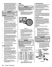
...back of the pivot pin (b) and then tighten the lock nut (a) on a furnace, water heater, clothes dryer, etc. 2. See Figure 4-7. 7. Remove the front gauge wheel (b), hex screw (c) and spacer (d). Off-Season Storage Tractor Storage If your hands by using heavy gloves when handling the blades. ...index hole of the just adjusted front gauge wheel (b), and adjust the other front gauge wheel bracket (e). Protect your Cub Cadet dealer to protect it is set the deck in a dry and protected location. The procedures outlined below . If stored outside blades so that will give the ...
...back of the pivot pin (b) and then tighten the lock nut (a) on a furnace, water heater, clothes dryer, etc. 2. See Figure 4-7. 7. Remove the front gauge wheel (b), hex screw (c) and spacer (d). Off-Season Storage Tractor Storage If your hands by using heavy gloves when handling the blades. ...index hole of the just adjusted front gauge wheel (b), and adjust the other front gauge wheel bracket (e). Protect your Cub Cadet dealer to protect it is set the deck in a dry and protected location. The procedures outlined below . If stored outside blades so that will give the ...
Operation Manual
Page 20
... with a 12-volt battery charger at a MAXIMUM rate of a pressure washer or garden hose is located beneath the seat frame. Transport Position/ Highest Mowing Position Deck Removal/ Installation Position Lowest Mowing Position Figure 4-11 20 Section 4 - Product Care Note: Use of 10 amps. Protect the metal surfaces. Note... serious burns. If a function of the safety interlock system described earlier is installed to protect the tractor's electrical system from forming in the reverse order. Deck Removal Remove the tractor deck from the negative battery post. 3.
... with a 12-volt battery charger at a MAXIMUM rate of a pressure washer or garden hose is located beneath the seat frame. Transport Position/ Highest Mowing Position Deck Removal/ Installation Position Lowest Mowing Position Figure 4-11 20 Section 4 - Product Care Note: Use of 10 amps. Protect the metal surfaces. Note... serious burns. If a function of the safety interlock system described earlier is installed to protect the tractor's electrical system from forming in the reverse order. Deck Removal Remove the tractor deck from the negative battery post. 3.
Operation Manual
Page 21
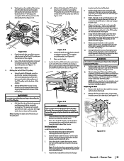
...the belt rearward and downward while manually turning the PTO pulley to step 6. 6. Lower the deck into the deck removal/ installation position using the deck lift handle. Slide the front deck lift rod off the hanger brackets on to the right until the belt rides out onto ... Make certain the 'V' belt is fully rolled into the deck removal/ installation position using the deck lift handle. While still holding and rotating the PTO pulley and PTO belt until the PTO belt (a) is not twisted; Refer to Deck Removal). 2. Continue holding the PTO belt (a) downward, continue turning...
...the belt rearward and downward while manually turning the PTO pulley to step 6. 6. Lower the deck into the deck removal/ installation position using the deck lift handle. Slide the front deck lift rod off the hanger brackets on to the right until the belt rides out onto ... Make certain the 'V' belt is fully rolled into the deck removal/ installation position using the deck lift handle. While still holding and rotating the PTO pulley and PTO belt until the PTO belt (a) is not twisted; Refer to Deck Removal). 2. Continue holding the PTO belt (a) downward, continue turning...
Operation Manual
Page 22
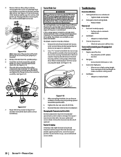
...belt guards (g) to hold the hex nut on the sharpened blades. Remove the belt from beneath the tractor, (refer to Deck Removal) then gently flip the deck over to Deck Installation). Install the new belt around the idler pulleys removed in step 3 with the "V" side facing in Figure 4-17 ...and then reinstall the deck (refer to expose its underside. 2. Place the belt around ...
...belt guards (g) to hold the hex nut on the sharpened blades. Remove the belt from beneath the tractor, (refer to Deck Removal) then gently flip the deck over to Deck Installation). Install the new belt around the idler pulleys removed in step 3 with the "V" side facing in Figure 4-17 ...and then reinstall the deck (refer to expose its underside. 2. Place the belt around ...


