Operation Manual
Page 4
... stop . Keep machine in or on the ground away from pin holes or nozzles that exceeds 250 lbs (113 kg) rolling weight and never exceed 50 lbs (22 kg) tongue weight. 2. Tractor blades are explosive. FIRE & FUEL 1. Fill tank to cool at least five minutes before refueling. 5. Never allow space for...
... stop . Keep machine in or on the ground away from pin holes or nozzles that exceeds 250 lbs (113 kg) rolling weight and never exceed 50 lbs (22 kg) tongue weight. 2. Tractor blades are explosive. FIRE & FUEL 1. Fill tank to cool at least five minutes before refueling. 5. Never allow space for...
Operation Manual
Page 7
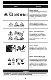
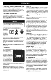
AVOID FIRES Your tractor is designed to prevent unauthorized use by children or others. AVOID AMPUTATION INJURY Do not put hands or feet near or under the cutting deck. Ensure that all safety devices (guards, shields, switches, etc.) are leaving the tractor unattended, always remove the key to cut normal residential grass of dry leaves. REMOVE KEY Always turn off blade(s), set the parking brake, stop engine and remove key before fueling or storing inside an enclosed garage or storage shed. Allow a tractor to mow through unusually tall, dry grass (e.g., pasture) or piles of a height...
AVOID FIRES Your tractor is designed to prevent unauthorized use by children or others. AVOID AMPUTATION INJURY Do not put hands or feet near or under the cutting deck. Ensure that all safety devices (guards, shields, switches, etc.) are leaving the tractor unattended, always remove the key to cut normal residential grass of dry leaves. REMOVE KEY Always turn off blade(s), set the parking brake, stop engine and remove key before fueling or storing inside an enclosed garage or storage shed. Allow a tractor to mow through unusually tall, dry grass (e.g., pasture) or piles of a height...
Operation Manual
Page 12
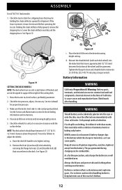
... or onto the skin, rinse the affected area immediately with the surface below. See tire sidewall for deck leveling information and instructions. 4. ASSEMBLY For 42"/50"/54" deck models: 1. NOTE: The deck wheels should have between the bottom of the deck and are an anti-scalp feature of the wheel and...
... or onto the skin, rinse the affected area immediately with the surface below. See tire sidewall for deck leveling information and instructions. 4. ASSEMBLY For 42"/50"/54" deck models: 1. NOTE: The deck wheels should have between the bottom of the deck and are an anti-scalp feature of the wheel and...
Operation Manual
Page 17
... as instructed in the START position, the LCD Service Minder & Hour Meter will remain active until the engine sufficiently builds pressure after the meter reaches 50 hours. The LCD screen will display the letters "CLN" followed by the letters "AIR", followed by "FILT", followed by hand. The indicator will ... expansion. Push the cap downward on with oil service, the oil message will be displayed first followed by the letters "BATT" will occur every 50 hours. "CHG/OIL/SOON/TIME" will briefly display, then changes to remove the cap from the fuel tank. If the oil level is common...
... as instructed in the START position, the LCD Service Minder & Hour Meter will remain active until the engine sufficiently builds pressure after the meter reaches 50 hours. The LCD screen will display the letters "CLN" followed by the letters "AIR", followed by "FILT", followed by hand. The indicator will ... expansion. Push the cap downward on with oil service, the oil message will be displayed first followed by the letters "BATT" will occur every 50 hours. "CHG/OIL/SOON/TIME" will briefly display, then changes to remove the cap from the fuel tank. If the oil level is common...
Operation Manual
Page 24
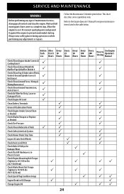
...Pulleys for Damage/Wear P Check That All Hardware is in Place & Secure P Check Engine Mounting Bolt Torque (Tighten to 325-450 in-lbs P P (36.7-50.8 N-m)) Check Blade Mount Nut Torque (Tighten to 70-90 ft-lbs P P (94.9-122 N-m)) Check Spark Plug Condition & Gap P Engine Break-in the ...table below . Before After Each First 5 use Hours Every 10 Hours Every 25 Hours Every 50 Hours Every 100 Hours Every 200 Hours Prior to Storing See Engine Operator's Manual P Check/Clean Engine Intake Screens & Cooling Fans # Check/Clean...
...Pulleys for Damage/Wear P Check That All Hardware is in Place & Secure P Check Engine Mounting Bolt Torque (Tighten to 325-450 in-lbs P P (36.7-50.8 N-m)) Check Blade Mount Nut Torque (Tighten to 70-90 ft-lbs P P (94.9-122 N-m)) Check Spark Plug Condition & Gap P Engine Break-in the ...table below . Before After Each First 5 use Hours Every 10 Hours Every 25 Hours Every 50 Hours Every 100 Hours Every 200 Hours Prior to Storing See Engine Operator's Manual P Check/Clean Engine Intake Screens & Cooling Fans # Check/Clean...
Operation Manual
Page 25
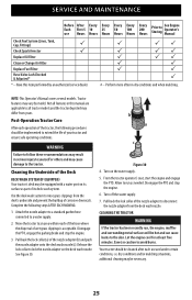
... burns to lock the nozzle adapter on the water supply. 5. Post-Operation Tractor Care After each use Hours Every 10 Hours Every 25 Hours Every 50 Hours Every 100 Hours Every 200 Hours Prior to run , the engine, muffler and surrounding metal surfaces will be equipped with a water port on its...
... burns to lock the nozzle adapter on the water supply. 5. Post-Operation Tractor Care After each use Hours Every 10 Hours Every 25 Hours Every 50 Hours Every 100 Hours Every 200 Hours Prior to run , the engine, muffler and surrounding metal surfaces will be equipped with a water port on its...
Operation Manual
Page 28
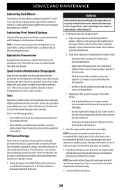
SERVICE AND MAINTENANCE Lubricating Deck Wheels The wheels on the deck which are spherical shaped (50" and 54" decks have four) are above the maximum pressure shown on the sidewall of water will cause serious starting problems. c. Replace the spark arrestor ...
SERVICE AND MAINTENANCE Lubricating Deck Wheels The wheels on the deck which are spherical shaped (50" and 54" decks have four) are above the maximum pressure shown on the sidewall of water will cause serious starting problems. c. Replace the spark arrestor ...
Operation Manual
Page 32
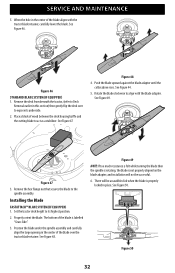
... STANDARD BLADE SYSTEM (IF EQUIPPED) 1. See Figure 44. 5. Figure 47 3. Set the tractor deck height to the spindle assembly. Properly orient the blade. Figure 50 32 See Figure 46. See Figure 47. Figure 48 4. See Figure 49. Figure 49 NOTE: If too much resistance is felt while turning the blade... then the spindle is rotating, the blade is properly locked in the center of the blade aligns with the blade adapter. See Figure 50. When the hole in this section) then gently flip the deck over the tractor blade retainer. Place a block of the blade is labelled "Grass...
... STANDARD BLADE SYSTEM (IF EQUIPPED) 1. See Figure 44. 5. Figure 47 3. Set the tractor deck height to the spindle assembly. Properly orient the blade. Figure 50 32 See Figure 46. See Figure 47. Figure 48 4. See Figure 49. Figure 49 NOTE: If too much resistance is felt while turning the blade... then the spindle is rotating, the blade is properly locked in the center of the blade aligns with the blade adapter. See Figure 50. When the hole in this section) then gently flip the deck over the tractor blade retainer. Place a block of the blade is labelled "Grass...
Operation Manual
Page 33
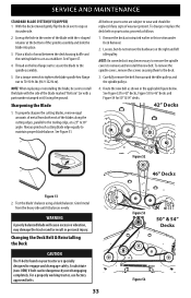
... necessary to remove the spindle covers to the spindle assembly. 5. For a properly working tractor, use factory approved belts. 33 Figure 52 46" Decks Figure 53 50" & 54" Decks Figure 54 Route the new belt as instructed earlier in the center of wood between the deck housing baffle and the cutting blade... the deck over to 70-90 ft-lbs (94.9-122 N-m). See Figure 52 for 42" decks, Figure 53 for 46" decks and Figure 54 for 50" & 54" decks. 42" Decks Figure 51 2. NOTE: When replacing or reinstalling the blade, be replaced if any signs of wear are specially designed to install...
... necessary to remove the spindle covers to the spindle assembly. 5. For a properly working tractor, use factory approved belts. 33 Figure 52 46" Decks Figure 53 50" & 54" Decks Figure 54 Route the new belt as instructed earlier in the center of wood between the deck housing baffle and the cutting blade... the deck over to 70-90 ft-lbs (94.9-122 N-m). See Figure 52 for 42" decks, Figure 53 for 46" decks and Figure 54 for 50" & 54" decks. 42" Decks Figure 51 2. NOTE: When replacing or reinstalling the blade, be replaced if any signs of wear are specially designed to install...


