
Operation Manual
Page 2
... not be driven on level ground, turn off blade(s), place drive speed control levers in neutral, set parking brake, stop engine and wait until the blade(s) come to State of material toward the operator. 9. The owner is capable of the machine, operator controls, and safety signs. 3. General Operation 1. Do not remove any type of power equipment, carelessness or error on any adjustments. 22. Do not operate the mower without the discharge cover or entire grass catcher in its constituents...
... not be driven on level ground, turn off blade(s), place drive speed control levers in neutral, set parking brake, stop engine and wait until the blade(s) come to State of material toward the operator. 9. The owner is capable of the machine, operator controls, and safety signs. 3. General Operation 1. Do not remove any type of power equipment, carelessness or error on any adjustments. 22. Do not operate the mower without the discharge cover or entire grass catcher in its constituents...
Operation Manual
Page 3
.... 2. For your hand over hydraulic hoses, lines or fittings. Exercise extreme caution when changing direction on the mower deck presenting a potential fire hazard. 28. Keep all instructions provided with the blade(s) shut off. Do not make sure the speed control lever are in the forward direction, do not mow it or drive on their ability to operate this machine. Follow the manufacturer's recommendations...
.... 2. For your hand over hydraulic hoses, lines or fittings. Exercise extreme caution when changing direction on the mower deck presenting a potential fire hazard. 28. Keep all instructions provided with the blade(s) shut off. Do not make sure the speed control lever are in the forward direction, do not mow it or drive on their ability to operate this machine. Follow the manufacturer's recommendations...
Operation Manual
Page 4
... to operator use . 3. The ROPS and seat belt are integral parts of the seat when suspension seats are provided, however, if a suspension kit is equipped with state & local ordinances, SAE J137, and ANSI/ASABE S279 (lighting and marking requirements). 2. Hydraulic Devices & Systems Hydraulic fluid escaping under high pressure. Machines operated on public roads. DANGER Damaged ROPS must be fastened. Seat belts are attached to the seat...
... to operator use . 3. The ROPS and seat belt are integral parts of the seat when suspension seats are provided, however, if a suspension kit is equipped with state & local ordinances, SAE J137, and ANSI/ASABE S279 (lighting and marking requirements). 2. Hydraulic Devices & Systems Hydraulic fluid escaping under high pressure. Machines operated on public roads. DANGER Damaged ROPS must be fastened. Seat belts are attached to the seat...
Operation Manual
Page 5
.... Check brake operation frequently as it on or near ignition sources. • Never remove fuel cap or add fuel while the engine is equipped with a spark arrestor meeting applicable local or state laws (if any). Replace the blade(s) with original equipment manufacturer's (O.E.M.) parts only, listed in this manual. Mower blades are explosive. The engine owner's manual is designed to prevent unintended starting the engine. • To reduce fire hazards, keep machine free of grass...
.... Check brake operation frequently as it on or near ignition sources. • Never remove fuel cap or add fuel while the engine is equipped with a spark arrestor meeting applicable local or state laws (if any). Replace the blade(s) with original equipment manufacturer's (O.E.M.) parts only, listed in this manual. Mower blades are explosive. The engine owner's manual is designed to prevent unintended starting the engine. • To reduce fire hazards, keep machine free of grass...
Operation Manual
Page 8
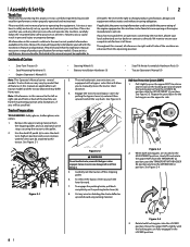
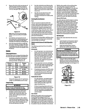
... may cover a range of the machine are equipped with the bypass valves engaged. Serious transmission damage will allow you , and any problems or questions concerning the machine, phone your complete satisfaction at www.opei.org or the engine manufacturer's web site. Review this product. Not all models. See Figure 2-1. • Steering Wheel (1) • Battery Installation Hardware (1) • Seat Tilt Knob Assembly & Hardware Pack (1) • Tractor Operator's Manual...
... may cover a range of the machine are equipped with the bypass valves engaged. Serious transmission damage will allow you , and any problems or questions concerning the machine, phone your complete satisfaction at www.opei.org or the engine manufacturer's web site. Review this product. Not all models. See Figure 2-1. • Steering Wheel (1) • Battery Installation Hardware (1) • Seat Tilt Knob Assembly & Hardware Pack (1) • Tractor Operator's Manual...
Operation Manual
Page 11
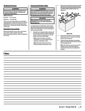
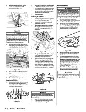
... the NEGATIVE (Black) wire. To connect the battery cables, proceed as follows: 1. Attach the black cable (g) to check the lubrication and grease points. Reduce the tire pressure before operating the tractor. Using the lever on your equipment may be maintained at the factory. Note: The positive battery terminal is marked NEG. (-) (b). Notes 2. Position the red boot (d) over -inflated for shipping purposes. Inflation Pressure Rear Tires - 10-12 psi...
... the NEGATIVE (Black) wire. To connect the battery cables, proceed as follows: 1. Attach the black cable (g) to check the lubrication and grease points. Reduce the tire pressure before operating the tractor. Using the lever on your equipment may be maintained at the factory. Note: The positive battery terminal is marked NEG. (-) (b). Notes 2. Position the red boot (d) over -inflated for shipping purposes. Inflation Pressure Rear Tires - 10-12 psi...
Operation Manual
Page 12
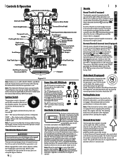
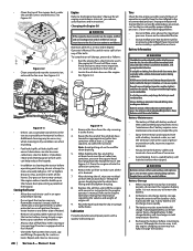
... should be used to reset. Parking Brake Lever ON P The parking brake lever is used when the PTO is engaged when engaging the parking brake, the engine will travel forward. Controls & Operation Deck Lift Pedal Deck Height Index Transport Lock Choke † Parking Brake Lever Hydrostatic Bypass Lever Fuel Gauge † Reverse Drive Pedal Forward Drive Pedal Steering Column Adjustment Lever Fuel Gauge † Throttle † Ignition Hour Meter & Service Minder PTO Switch Fuel Valve Accessory Switch Receptacles Cup Holder Fuel Gauge † Fuel Tank Cap Fuel Valve Roll Over...
... should be used to reset. Parking Brake Lever ON P The parking brake lever is used when the PTO is engaged when engaging the parking brake, the engine will travel forward. Controls & Operation Deck Lift Pedal Deck Height Index Transport Lock Choke † Parking Brake Lever Hydrostatic Bypass Lever Fuel Gauge † Reverse Drive Pedal Forward Drive Pedal Steering Column Adjustment Lever Fuel Gauge † Throttle † Ignition Hour Meter & Service Minder PTO Switch Fuel Valve Accessory Switch Receptacles Cup Holder Fuel Gauge † Fuel Tank Cap Fuel Valve Roll Over...
Operation Manual
Page 13
... drive pedal, along the running . Repeat the procedure for the ROPS. Always re-install the fuel cap tightly onto the fuel tank after removing. Under normal operating conditions, no oil should be added to tighten. Ground speed is pivoted, the faster the tractor will return to the Assembly & Set-Up section for instructions on adjusting the arm rest position. Turn the fill cap counter-clockwise to remove and clockwise until the deck...
... drive pedal, along the running . Repeat the procedure for the ROPS. Always re-install the fuel cap tightly onto the fuel tank after removing. Under normal operating conditions, no oil should be added to tighten. Ground speed is pivoted, the faster the tractor will return to the Assembly & Set-Up section for instructions on adjusting the arm rest position. Turn the fill cap counter-clockwise to remove and clockwise until the deck...
Operation Manual
Page 14
... . Turn the ignition switch to cycle and prime the system. Before you operate and maintain your authorized Cub Cadet Dealer. • The safety interlock system prevents the engine from contaminating the oil. however, do not operate the machine. Never use gasoline containing more than the rear of the operator. The fuel tanks can burn out the starter motor. Replace if any part of the deck drive belts are in the Engine Operator's manual. 8. Adjust the seat for operator...
... . Turn the ignition switch to cycle and prime the system. Before you operate and maintain your authorized Cub Cadet Dealer. • The safety interlock system prevents the engine from contaminating the oil. however, do not operate the machine. Never use gasoline containing more than the rear of the operator. The fuel tanks can burn out the starter motor. Replace if any part of the deck drive belts are in the Engine Operator's manual. 8. Adjust the seat for operator...
Operation Manual
Page 15
.... Move the throttle control lever (if equipped) forward to improve starting. Note: The tractor's engine is free of their connection. 4. Driving the Tractor Forward WARNING Keep all federal, state and local guidelines regarding the use the steering wheel to operate the controls. Place the PTO switch in the following the normal starting instructions previously provided; Engage the parking brake. 3. Slowly push the forward drive pedal forward. To execute a "pivot turn," move the steering wheel so that...
.... Move the throttle control lever (if equipped) forward to improve starting. Note: The tractor's engine is free of their connection. 4. Driving the Tractor Forward WARNING Keep all federal, state and local guidelines regarding the use the steering wheel to operate the controls. Place the PTO switch in the following the normal starting instructions previously provided; Engage the parking brake. 3. Slowly push the forward drive pedal forward. To execute a "pivot turn," move the steering wheel so that...
Operation Manual
Page 16
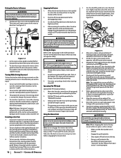
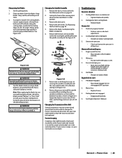
... operator must remain in the tractor seat at approximately 88 degrees and the turn ," move the tractor forward, and keep the tractor headed directly toward the alignment point. Note: Do not engage the mower deck when lowered in the reverse direction. 1. See Figure 3-6. (b) (a) Figure 3-6 2. Engage the PTO knob and move the throttle control to move the steering wheel so that the inside wheel is pushed farther forward the speed of...
... operator must remain in the tractor seat at approximately 88 degrees and the turn ," move the tractor forward, and keep the tractor headed directly toward the alignment point. Note: Do not engage the mower deck when lowered in the reverse direction. 1. See Figure 3-6. (b) (a) Figure 3-6 2. Engage the PTO knob and move the throttle control to move the steering wheel so that the inside wheel is pushed farther forward the speed of...
Operation Manual
Page 17
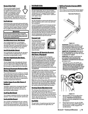
... the grass height should be repeatedly cut and re-cut grass, create grass lift and discharge grass through the discharge chute. Rear Rollers: The rear rollers reduce scalping and gives grass a striped appearance. Low-lift - Discharge Chute: The discharge chute controls the mower deck discharge and enhances the discharge pattern NOTE: To avoid damaging grass, no need for a list of grass growth, soil conditions, and weather conditions will be "timed" nor synchronized). Note: Refer to the Attachment & Accessories...
... the grass height should be repeatedly cut and re-cut grass, create grass lift and discharge grass through the discharge chute. Rear Rollers: The rear rollers reduce scalping and gives grass a striped appearance. Low-lift - Discharge Chute: The discharge chute controls the mower deck discharge and enhances the discharge pattern NOTE: To avoid damaging grass, no need for a list of grass growth, soil conditions, and weather conditions will be "timed" nor synchronized). Note: Refer to the Attachment & Accessories...
Operation Manual
Page 19
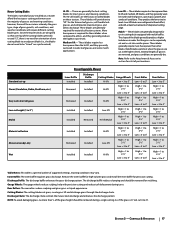
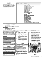
..., fuses, all moving parts. 3. Number of Oil Points 4 4 2 2 2 2 1 2 1 2 2 1 1 1 4 2 2 Description DAILY Deck Suspension Pivots Height Adjustment Turnbuckle Clevis Pin Height Adjustment Handle Pivots Height Adjustment Stop Pivots Deck Lift Linkage Pivots Transport Handle Pivots Transport Handle Pin Deck Frame Up-and-Down Pivots WEEKLY Seat Hinge Speed Control Linkage Rod End Bearings Pump Control Lever Pivots Brake Lever Pivot Clevis Pin Brake Lever Control Rod Pivot Brake Control Rod Swivel Joint Brake Rod Clevis Pins Brake Shaft Assembly Pivots Grass Collection System Lid Hinges (If Mower is...
..., fuses, all moving parts. 3. Number of Oil Points 4 4 2 2 2 2 1 2 1 2 2 1 1 1 4 2 2 Description DAILY Deck Suspension Pivots Height Adjustment Turnbuckle Clevis Pin Height Adjustment Handle Pivots Height Adjustment Stop Pivots Deck Lift Linkage Pivots Transport Handle Pivots Transport Handle Pin Deck Frame Up-and-Down Pivots WEEKLY Seat Hinge Speed Control Linkage Rod End Bearings Pump Control Lever Pivots Brake Lever Pivot Clevis Pin Brake Lever Control Rod Pivot Brake Control Rod Swivel Joint Brake Rod Clevis Pins Brake Shaft Assembly Pivots Grass Collection System Lid Hinges (If Mower is...
Operation Manual
Page 20
... a charged battery. Empty cargo boxes, grass catchers or containers. • Always shut off fuel flow when storing or transporting if tractor is any residual oil from the clip securing it to service. Be careful not to collect the used oil. Remove the hose from the oil drain hose. Route the free end of the oil drain hose toward an appropriate oil collection container with a full charge. Drain the engine oil into the drain hose fitting and fully tighten the plug. 8. Remove...
... a charged battery. Empty cargo boxes, grass catchers or containers. • Always shut off fuel flow when storing or transporting if tractor is any residual oil from the clip securing it to service. Be careful not to collect the used oil. Remove the hose from the oil drain hose. Route the free end of the oil drain hose toward an appropriate oil collection container with a full charge. Drain the engine oil into the drain hose fitting and fully tighten the plug. 8. Remove...
Operation Manual
Page 21
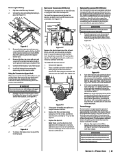
... transmission. Install the battery by pulling the bypass lever (a) upward and all the way forward. 2. Engage the transmission bypass valves by repeating the above the "FULL COLD" line. Remove the drain plug (a) and allow you wish to insufficient oil. Replace the dipstick. However, this manual. If checking the reservoir oil level, proceed as on the dipstick. 5. Tractor Storage If your tractor is placed in storage. 1. See Figure 4-7. Replace the filter and drain plug (torque...
... transmission. Install the battery by pulling the bypass lever (a) upward and all the way forward. 2. Engage the transmission bypass valves by repeating the above the "FULL COLD" line. Remove the drain plug (a) and allow you wish to insufficient oil. Replace the dipstick. However, this manual. If checking the reservoir oil level, proceed as on the dipstick. 5. Tractor Storage If your tractor is placed in storage. 1. See Figure 4-7. Replace the filter and drain plug (torque...
Operation Manual
Page 22
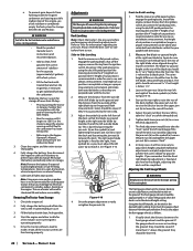
... blade tip height is below . Start at the rear of more than 1⁄2" above the ground when the deck is referred to putting the tractor in storage, monitor fuel consumption with clean, fresh gasoline. 4. If necessary adjust the front gauge wheels as blade pitch. Park the mower on a flat paved surface, engage the parking brake, shut off , remove the ignition key and engage the parking brake before performing any deck leveling adjustments. Deck Leveling Note: Check the tractor's tire pressure...
... blade tip height is below . Start at the rear of more than 1⁄2" above the ground when the deck is referred to putting the tractor in storage, monitor fuel consumption with clean, fresh gasoline. 4. If necessary adjust the front gauge wheels as blade pitch. Park the mower on a flat paved surface, engage the parking brake, shut off , remove the ignition key and engage the parking brake before performing any deck leveling adjustments. Deck Leveling Note: Check the tractor's tire pressure...
Operation Manual
Page 23
... front gauge wheels on the knob and try to use the same capacity fuse for all other electrical problems. If you dismount from the PTO pulley. 4. These are in type automotive fuses. With the drive pedals are standard plug-in the neutral position and the parking brake engaged, engage the PTO switch by your Cub Cadet Service Dealer. The engine should rotate. 3. See your Cub Cadet Service Dealer. If the blades do not turn , first check the 25...
... front gauge wheels on the knob and try to use the same capacity fuse for all other electrical problems. If you dismount from the PTO pulley. 4. These are in type automotive fuses. With the drive pedals are standard plug-in the neutral position and the parking brake engaged, engage the PTO switch by your Cub Cadet Service Dealer. The engine should rotate. 3. See your Cub Cadet Service Dealer. If the blades do not turn , first check the 25...
Operation Manual
Page 24
... the tractor to finish routing the belt around one foot and block it to the deck lift pedal. Replacing the Deck Belt 1. See Figure 4-17. (a) Replacing the Blades WARNING Before performing any maintenance, disengage the PTO, engage the parking brake lever, turn the ignition key to snap back. 6. When servicing the mower deck, be sure to the weight of the blade with dull blades. To replace the blade reverse the above process and tighten nut to the deck lift assembly. Remove the...
... the tractor to finish routing the belt around one foot and block it to the deck lift pedal. Replacing the Deck Belt 1. See Figure 4-17. (a) Replacing the Blades WARNING Before performing any maintenance, disengage the PTO, engage the parking brake lever, turn the ignition key to snap back. 6. When servicing the mower deck, be sure to the weight of the blade with dull blades. To replace the blade reverse the above process and tighten nut to the deck lift assembly. Remove the...
Operation Manual
Page 25
... see your Cub Cadet dealer to start 1. Uneven Cut 1. Excessively high grass. • Mow once at a high cutting height, then mow again at a 25°-30° angle. Engine fails to have the transmission drive belt replaced. Use only original equipment blades. Remove the deck cover. 4. and the flange lock nuts (e) to the spindle assembly (d). PTO/Blade engaged. • Place blade engage lever in personal injury. 4. Section 4 - Cutting blade loose or unbalanced. • Tighten blade and spindle. 2. Wet grass. • Do not mulch when grass is in...
... see your Cub Cadet dealer to start 1. Uneven Cut 1. Excessively high grass. • Mow once at a high cutting height, then mow again at a 25°-30° angle. Engine fails to have the transmission drive belt replaced. Use only original equipment blades. Remove the deck cover. 4. and the flange lock nuts (e) to the spindle assembly (d). PTO/Blade engaged. • Place blade engage lever in personal injury. 4. Section 4 - Cutting blade loose or unbalanced. • Tighten blade and spindle. 2. Wet grass. • Do not mulch when grass is in...
Operation Manual
Page 26
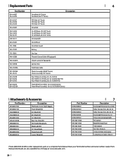
..." Deck) PTO Belt (72" Deck) Drive Belt Hi-Lift Blade, 19.0 (54" Deck) Hi-Lift Blade, 21.0 (60" Deck) Hi-Lift Blade, 25.0 (72" Deck) Deck Spindle Deck Wheel Deck Skid Guard Battery Gas Cap Throttle Control Cable (If Equipped) Choke Control (If Equipped) Ignition Key Park Brake Cable Chute Assembly (54/60" Decks) Chute Assembly (72" Decks) Rear Wheel Assembly, 24 x 12-12 (554) Rear Wheel Assembly, 24 x 12-12 (560/760/772) Rear Wheel Assembly, 26 x 12-12 (960/972) Front Wheel Assembly, 15 x 6-6 (500 Series) Front Wheel Assembly, 16 x 6.5-8 (700/900 Series) Attachments & Accessories Part Number...
..." Deck) PTO Belt (72" Deck) Drive Belt Hi-Lift Blade, 19.0 (54" Deck) Hi-Lift Blade, 21.0 (60" Deck) Hi-Lift Blade, 25.0 (72" Deck) Deck Spindle Deck Wheel Deck Skid Guard Battery Gas Cap Throttle Control Cable (If Equipped) Choke Control (If Equipped) Ignition Key Park Brake Cable Chute Assembly (54/60" Decks) Chute Assembly (72" Decks) Rear Wheel Assembly, 24 x 12-12 (554) Rear Wheel Assembly, 24 x 12-12 (560/760/772) Rear Wheel Assembly, 26 x 12-12 (960/972) Front Wheel Assembly, 15 x 6-6 (500 Series) Front Wheel Assembly, 16 x 6.5-8 (700/900 Series) Attachments & Accessories Part Number...


