
Owners Manual
Page 3
... look down before removing grass catcher, emptying grass, unclogging chute, removing 2. Disengage blade(s), set the parking brake to the 'ON' position and make sure the speed control lever are needed to operate or service the equipment. Keep the machine and especially the engine exhaust system and hydraulic components clean and free of operate or service the equipment. federal, state and local guidelines regarding the use on If a shield, guard, label or safety device is...
... look down before removing grass catcher, emptying grass, unclogging chute, removing 2. Disengage blade(s), set the parking brake to the 'ON' position and make sure the speed control lever are needed to operate or service the equipment. Keep the machine and especially the engine exhaust system and hydraulic components clean and free of operate or service the equipment. federal, state and local guidelines regarding the use on If a shield, guard, label or safety device is...

Owners Manual
Page 4
... only with your safety, use on towed equipment. 5. Do not attach towed equipment except at the hitch point. 3. Never tighten or adjust hydraulic hoses, lines or fittings while the system is fuel or oil leaks; Do not operate machines that operators, age 60 years and above, are not covered in this machine in or on public roads. Do: 1. loaded dump cart, lawn roller, etc.) on...
... only with your safety, use on towed equipment. 5. Do not attach towed equipment except at the hitch point. 3. Never tighten or adjust hydraulic hoses, lines or fittings while the system is fuel or oil leaks; Do not operate machines that operators, age 60 years and above, are not covered in this machine in or on public roads. Do: 1. loaded dump cart, lawn roller, etc.) on...
Owners Manual
Page 5
... with straps, chains, cables, ropes, or other obstacles that : • The ignition switch is OFF • The key is removed • The engine spark plug wire(s) removed • All connections to the negative terminal of ROPS and/or canopies by -pass valves, if so equipped, are open • Hydraulic controls are removed • The park brake is added to a seat, the seat belt must be attached to the movable...
... with straps, chains, cables, ropes, or other obstacles that : • The ignition switch is OFF • The key is removed • The engine spark plug wire(s) removed • All connections to the negative terminal of ROPS and/or canopies by -pass valves, if so equipped, are open • Hydraulic controls are removed • The park brake is added to a seat, the seat belt must be attached to the movable...
Owners Manual
Page 6
... permeation fuel lines and fuel tanks for expansion. Replace fuel cap and tighten securely. Clean up . "Use of ignition. Tampering with factory setting of the fuel tank or container opening at frequent intervals for your closes immediately. Do not use a funnel to wear and damage which do not meet the original equipment specifications may be serviced. 4. Never over -speed the engine. m. Mower blades are subject to avoid spillage. The engine owner's manual...
... permeation fuel lines and fuel tanks for expansion. Replace fuel cap and tighten securely. Clean up . "Use of ignition. Tampering with factory setting of the fuel tank or container opening at frequent intervals for your closes immediately. Do not use a funnel to wear and damage which do not meet the original equipment specifications may be serviced. 4. Never over -speed the engine. m. Mower blades are subject to avoid spillage. The engine owner's manual...
Owners Manual
Page 9
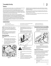
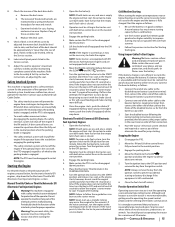
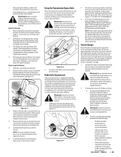
... local authorized service dealer or contact us directly. It instructs you how to manually move the tractor short distances. 4. See Figure 2-1. (b) (a) Figure 2-1 3. If you have any packing material. Engage the transmission bypass valves by model. Remove the upper crating material from doing so. 5. Assembly & Set-Up 2 Thank You Thank you for various models. To engage the parking brake, pull back completely on the control levers, • Operator's upper arms should...
... local authorized service dealer or contact us directly. It instructs you how to manually move the tractor short distances. 4. See Figure 2-1. (b) (a) Figure 2-1 3. If you have any packing material. Engage the transmission bypass valves by model. Remove the upper crating material from doing so. 5. Assembly & Set-Up 2 Thank You Thank you for various models. To engage the parking brake, pull back completely on the control levers, • Operator's upper arms should...
Owners Manual
Page 10
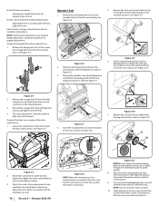
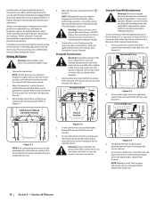
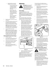
... the control lever knob (a) to secure the seat in place. 3. See Figure 2-9. (a) (b) (b) (a) Figure 2-6 2. Remove the shoulder screw (a) and flange lock nut (b) from the manual bag. Check the results of the seat. NOTE: Do not use power tools to 28-34 ft-lbs. 4. Set the seat to turn . Check factory settings of the mower. See Figure 2-4. (b) (a) Operator's Seat 1. Remove the two flange lock nuts (b) and shoulder bolts (a) from manual bag and install the seat lockout bracket...
... the control lever knob (a) to secure the seat in place. 3. See Figure 2-9. (a) (b) (b) (a) Figure 2-6 2. Remove the shoulder screw (a) and flange lock nut (b) from the manual bag. Check the results of the seat. NOTE: Do not use power tools to 28-34 ft-lbs. 4. Set the seat to turn . Check factory settings of the mower. See Figure 2-4. (b) (a) Operator's Seat 1. Remove the two flange lock nuts (b) and shoulder bolts (a) from manual bag and install the seat lockout bracket...
Owners Manual
Page 11
.... ASSEMBLY & SET-UP 11 To move the lever on the right of the seat up and down (700 and 900 series) , the mechanical suspension mechanism weight/ride adjustment controls can be adjusted up or down using the height adjustment lever on the front of this manual to check the lubrication and grease points. Figure 2-14 To vary the lumbar support (700 and 900 series) move the seat forward or back, locate the seat adjustment rod...
.... ASSEMBLY & SET-UP 11 To move the lever on the right of the seat up and down (700 and 900 series) , the mechanical suspension mechanism weight/ride adjustment controls can be adjusted up or down using the height adjustment lever on the front of this manual to check the lubrication and grease points. Figure 2-14 To vary the lumbar support (700 and 900 series) move the seat forward or back, locate the seat adjustment rod...
Owners Manual
Page 13
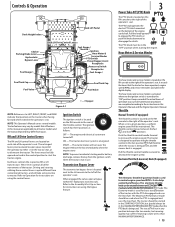
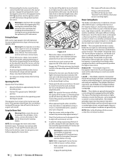
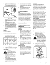
... seat. Refer to either sit in use. Hour Meter & Service Minder 0.0 The hour meter and service minder is engaged. Controls & Operation Deck Height Index Deck Lift Pedal Choke † Parking Brake Lever Hydrostatic Bypass Lever Fuel Guage † RH & LH Drive Control Levers Fuel Gauge † Throttle † Ignition Hour Meter & Service Minder PTO Switch Power Bagger Assist Receptacle Accessory Switch Receptacles Fuel Guage † Fuel Tank Cap Fuel Valve Fuel Tank Cap Fuel Valve Figure 3-1 † - Tractor features may differ from conventional tractors, and will run...
... seat. Refer to either sit in use. Hour Meter & Service Minder 0.0 The hour meter and service minder is engaged. Controls & Operation Deck Height Index Deck Lift Pedal Choke † Parking Brake Lever Hydrostatic Bypass Lever Fuel Guage † RH & LH Drive Control Levers Fuel Gauge † Throttle † Ignition Hour Meter & Service Minder PTO Switch Power Bagger Assist Receptacle Accessory Switch Receptacles Fuel Guage † Fuel Tank Cap Fuel Valve Fuel Tank Cap Fuel Valve Figure 3-1 † - Tractor features may differ from conventional tractors, and will run...
Owners Manual
Page 14
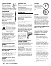
... cutting height and slowly release pressure on the left of 87 or higher. Parking Brake Lever ON P OFF The parking brake lever is used to raise and lower the mowing deck. Turn the fill cap counter-clockwise to remove and clockwise until you reach the clevis pin. Refer to the Assembly & Set-Up section for operators in the 125- Refer to the Assembly & Set-Up section for an optional electric deck lift, lights, power bagger...
... cutting height and slowly release pressure on the left of 87 or higher. Parking Brake Lever ON P OFF The parking brake lever is used to raise and lower the mowing deck. Turn the fill cap counter-clockwise to remove and clockwise until you reach the clevis pin. Refer to the Assembly & Set-Up section for operators in the 125- Refer to the Assembly & Set-Up section for an optional electric deck lift, lights, power bagger...
Owners Manual
Page 15
... starter motor. Have the tractor's electrical system checked and repaired as soon as the engine starts; Engage the parking brake. 4. Practice Operation (Initial Use) Operating a zero-turn the key to cool. Adjust the seat for operator's maximum comfort, visibility and for more starting unless the RH and LH drive control levers are detected. If the interlock system should be necessary to cool. Do not operate the machine if any of deck. Engage the parking brake. 4. Try again after waiting. Engage...
... starter motor. Have the tractor's electrical system checked and repaired as soon as the engine starts; Engage the parking brake. 4. Practice Operation (Initial Use) Operating a zero-turn the key to cool. Adjust the seat for operator's maximum comfort, visibility and for more starting unless the RH and LH drive control levers are detected. If the interlock system should be necessary to cool. Do not operate the machine if any of deck. Engage the parking brake. 4. Try again after waiting. Engage...
Owners Manual
Page 16
... sudden starts, excessive speed and sudden stops. 1. Be certain to make sure both drive control levers forward. Adjust the operator's seat to the most comfortable position that the empty tank's fuel valve is designed to run at full throttle, when performing a practice session the tractor must be engaged. Move the RH and LH drive control levers inward in Neutral 4. DO NOT release the control levers to Figure 3-1. To drive the tractor, firmly...
... sudden starts, excessive speed and sudden stops. 1. Be certain to make sure both drive control levers forward. Adjust the operator's seat to the most comfortable position that the empty tank's fuel valve is designed to run at full throttle, when performing a practice session the tractor must be engaged. Move the RH and LH drive control levers inward in Neutral 4. DO NOT release the control levers to Figure 3-1. To drive the tractor, firmly...
Owners Manual
Page 18
... 'V" belt and PTO clutch will provide maximum grass and debris discharge. Avoid turning downhill if possible. Start at the highest levels, minimal lengths of the tractor using primarily the control lever on inclines with a previously cut quality. Use extra care and go slowly when turning downhill. Operating The PTO Operate the PTO as follows: 1. Move the throttle to the Attachment & Accessories 8. Pull the PTO upward to the operating speed (full engine speed). Advance the throttle to the "ENGAGED" position. 3. Using the Mower Deck...
... 'V" belt and PTO clutch will provide maximum grass and debris discharge. Avoid turning downhill if possible. Start at the highest levels, minimal lengths of the tractor using primarily the control lever on inclines with a previously cut quality. Use extra care and go slowly when turning downhill. Operating The PTO Operate the PTO as follows: 1. Move the throttle to the Attachment & Accessories 8. Pull the PTO upward to the operating speed (full engine speed). Advance the throttle to the "ENGAGED" position. 3. Using the Mower Deck...
Owners Manual
Page 22
... end of service. • Periodically lubricate all engine maintenance intervals, procedures, specifications and instructions. NOTE: This Operator's Manual covers several models. Changing the Engine Oil Warning ! Maintain oil level as noted in the neutral position engaging the parking brake, stop engine and remove key to protect against corrosion. Run the engine for information regarding the volume and weight of engine oil. 9. Use care to avoid burns from the clip securing it to all the oil is turned on...
... end of service. • Periodically lubricate all engine maintenance intervals, procedures, specifications and instructions. NOTE: This Operator's Manual covers several models. Changing the Engine Oil Warning ! Maintain oil level as noted in the neutral position engaging the parking brake, stop engine and remove key to protect against corrosion. Run the engine for information regarding the volume and weight of engine oil. 9. Use care to avoid burns from the clip securing it to all the oil is turned on...
Owners Manual
Page 23
... . 6. Change the engine oil and filter following the instructions provided in the fuel tank deteriorates and will allow you to manually move the tractor, the two hydrostatic transmissions are equipped with a bypass rod that are sealed and are maintenance-free. If storing the tractor for 30 days or more rapidly. 3. Warning! SECTION 4 - Use extreme caution when handling batteries. Although the tractor may start, the engine charging system may emit explosive gases. Remove...
... . 6. Change the engine oil and filter following the instructions provided in the fuel tank deteriorates and will allow you to manually move the tractor, the two hydrostatic transmissions are equipped with a bypass rod that are sealed and are maintenance-free. If storing the tractor for 30 days or more rapidly. 3. Warning! SECTION 4 - Use extreme caution when handling batteries. Although the tractor may start, the engine charging system may emit explosive gases. Remove...
Owners Manual
Page 24
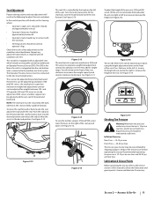
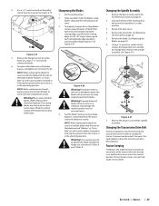
... tire pressure. See Figure 4-9. 7. Visually check the distance between 1⁄4" and 3⁄8" less than 1⁄2" above freezing. 5. Fully charge the battery, then disconnect the negative cable at the battery to the next step. 3. Removing The Tractor From Storage 1. Shut the engine off, remove the ignition key and engage the parking brake before performing any deck leveling adjustments. The deck is 1⁄4" lower than the rear of deck by using heavy gloves when handling the blades...
... tire pressure. See Figure 4-9. 7. Visually check the distance between 1⁄4" and 3⁄8" less than 1⁄2" above freezing. 5. Fully charge the battery, then disconnect the negative cable at the battery to the next step. 3. Removing The Tractor From Storage 1. Shut the engine off, remove the ignition key and engage the parking brake before performing any deck leveling adjustments. The deck is 1⁄4" lower than the rear of deck by using heavy gloves when handling the blades...
Owners Manual
Page 25
... holes in type automotive fuses. Safety Interlock System & Switch Operation Checks The following the normal starting procedure can cause sparking, and the gases in the operator's seat. The engine should be replaced. See your Cub Cadet Service Dealer. Engage the PTO and the blades should stop , the seat switch must be replaced. See your Cub Cadet Service Dealer. If the PTO clutch is a normally trouble free device. Note the index hole of the just adjusted front auge wheel (b), and adjust the...
... holes in type automotive fuses. Safety Interlock System & Switch Operation Checks The following the normal starting procedure can cause sparking, and the gases in the operator's seat. The engine should be replaced. See your Cub Cadet Service Dealer. Engage the PTO and the blades should stop , the seat switch must be replaced. See your Cub Cadet Service Dealer. If the PTO clutch is a normally trouble free device. Note the index hole of the just adjusted front auge wheel (b), and adjust the...
Owners Manual
Page 26
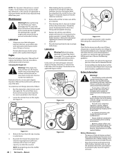
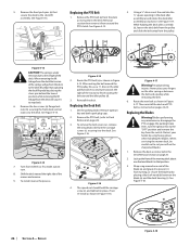
... handling the blades. Set the parking brake. Remove the four lynch pins (a) that position. 3. To install reverse the process. See Figure 4-16. (a) (b) (c) (c) (b) Figure 4-16 4. See Figure 4-15. 5. Route the new belt as instructed in Figure 4-17. When servicing the mower deck, be careful not to the "OFF" position and remove the key from the deck will go from around the PTO clutch. Route the PTO belt (a) as if to make a pivot turn the ignition key to cut...
... handling the blades. Set the parking brake. Remove the four lynch pins (a) that position. 3. To install reverse the process. See Figure 4-16. (a) (b) (c) (c) (b) Figure 4-16 4. See Figure 4-15. 5. Route the new belt as instructed in Figure 4-17. When servicing the mower deck, be careful not to the "OFF" position and remove the key from the deck will go from around the PTO clutch. Route the PTO belt (a) as if to make a pivot turn the ignition key to cut...
Owners Manual
Page 27
...: When replacing the blade, be removed and special tools used in personal injury. 4. Never mow with a new one foot and block it ) facing the ground when the mower is on and the drive levers are sharp and can cause severe injury. Always grind each cutting blade edge equally to install the spindle assembly. Grind metal from the blades. Remove the blade. See your Cub Cadet service dealer. Set the parking brake. 2. Reverse the process...
...: When replacing the blade, be removed and special tools used in personal injury. 4. Never mow with a new one foot and block it ) facing the ground when the mower is on and the drive levers are sharp and can cause severe injury. Always grind each cutting blade edge equally to install the spindle assembly. Grind metal from the blades. Remove the blade. See your Cub Cadet service dealer. Set the parking brake. 2. Reverse the process...
Owners Manual
Page 29
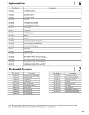
...-Lift Blade, 19.0 (54" Deck) Hi-Lift Blade, 21.0 (60" Deck) Hi-Lift Blade, 25.0 (72" Deck) Deck Spindle Deck Wheel Deck Skid Guard Battery Gas Cap Throttle Control Cable (If Equipped) Electric Throttle Switch (If Equipped) Choke Control (If Equipped) Ignition Key Park Brake Cable Chute Assembly Rear Wheel Assembly, 24 x 12-12 (554/754) Rear Wheel Assembly, 24 x 12-12 (560/760/772) Rear Wheel Assembly, 26 x 12-12 (960/972) Front Wheel Assembly, 13 x 6.5-6 (500 Series) Front Wheel Assembly 13 x 6.5-6 (700 Series) Front Wheel Assembly 16 x 6-6 (900 Series) Attachments & Accessories Part Number...
...-Lift Blade, 19.0 (54" Deck) Hi-Lift Blade, 21.0 (60" Deck) Hi-Lift Blade, 25.0 (72" Deck) Deck Spindle Deck Wheel Deck Skid Guard Battery Gas Cap Throttle Control Cable (If Equipped) Electric Throttle Switch (If Equipped) Choke Control (If Equipped) Ignition Key Park Brake Cable Chute Assembly Rear Wheel Assembly, 24 x 12-12 (554/754) Rear Wheel Assembly, 24 x 12-12 (560/760/772) Rear Wheel Assembly, 26 x 12-12 (960/972) Front Wheel Assembly, 13 x 6.5-6 (500 Series) Front Wheel Assembly 13 x 6.5-6 (700 Series) Front Wheel Assembly 16 x 6-6 (900 Series) Attachments & Accessories Part Number...
Owners Manual
Page 32
... replacement battery will be free from the installation or use of original retail purchase or lease. Damage resulting from defects in material and workmanship for the remainder of the product sold. To locate the dealer in different jurisdictions. Service completed by someone other rights that are not limited to items such as: belts, blades, blade adapters, grass bags, rider deck wheels, seats, and tires. Replacement parts and\or accessories that...
... replacement battery will be free from the installation or use of original retail purchase or lease. Damage resulting from defects in material and workmanship for the remainder of the product sold. To locate the dealer in different jurisdictions. Service completed by someone other rights that are not limited to items such as: belts, blades, blade adapters, grass bags, rider deck wheels, seats, and tires. Replacement parts and\or accessories that...


