
Owners Manual
Page 3
... and engine become hot and can cause serious personal injury. 25. Disengage the blades, set parking brake, stop or park the machine over . 29. Evaluate the terrain to a complete stop the machine and disengage the controls quickly. 21. Long hair, loose fitting clothing or jewelry may alcohol or drugs. A missing or damaged discharge cover can prevent and is not intended for use accessories and attachments approved...
... and engine become hot and can cause serious personal injury. 25. Disengage the blades, set parking brake, stop or park the machine over . 29. Evaluate the terrain to a complete stop the machine and disengage the controls quickly. 21. Long hair, loose fitting clothing or jewelry may alcohol or drugs. A missing or damaged discharge cover can prevent and is not intended for use accessories and attachments approved...

Owners Manual
Page 4
... push the machine and may cause loss of traction and loss of control (e.g. Avoid starting or stopping. 37. Keep all movements on wet grass. then turn over if a wheel is over the Machines operated on the ground. 5. Do not mow on the slopes slow and gradual. When going downhill, the extra weight tends to overturn). machine may speed up, braking and steering...
... push the machine and may cause loss of traction and loss of control (e.g. Avoid starting or stopping. 37. Keep all movements on wet grass. then turn over if a wheel is over the Machines operated on the ground. 5. Do not mow on the slopes slow and gradual. When going downhill, the extra weight tends to overturn). machine may speed up, braking and steering...
Owners Manual
Page 5
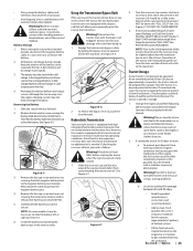
... is equipped with retractable function. 2. WARNING: Make sure all hydraulic fluid connections are tight and all times when the operator is set • All by items such as trees, buildings, doorways, clothes lines, utility wires, etc., that : • The ignition switch is OFF • The key is removed • The engine spark plug wire(s) removed • All connections to the system. SECTION 2 -
... is equipped with retractable function. 2. WARNING: Make sure all hydraulic fluid connections are tight and all times when the operator is set • All by items such as trees, buildings, doorways, clothes lines, utility wires, etc., that : • The ignition switch is OFF • The key is removed • The engine spark plug wire(s) removed • All connections to the system. SECTION 2 -
Owners Manual
Page 6
... ignition sources. Never remove fuel cap or add fuel while the engine is running . h. Never over -speed the engine. Replace fuel cap and tighten securely. Wait 5 minutes before resuming operation. 11. l. m. If the blades do not meet the original equipment specifications may lead to improper performance and compromise safety!" 8. "Use of ignition. Never attempt to make adjustments or repairs to the machine while the engine is hot or running . 12. For safety protection, frequently check...
... ignition sources. Never remove fuel cap or add fuel while the engine is running . h. Never over -speed the engine. Replace fuel cap and tighten securely. Wait 5 minutes before resuming operation. 11. l. m. If the blades do not meet the original equipment specifications may lead to improper performance and compromise safety!" 8. "Use of ignition. Never attempt to make adjustments or repairs to the machine while the engine is hot or running . 12. For safety protection, frequently check...
Owners Manual
Page 9
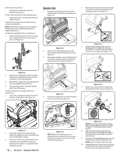
.... Serious transmission damage will result in place with the bypass valves engaged. If applicable, the power testing information used to provide excellent performance when properly operated and maintained. It was carefully engineered to establish the power rating of Carton • Zero-Turn Tractor (1) • Battery Installation Hardware (1) • Seat Tilt Knob Assembly & Hardware Pack (1) • Seat Mounting Hardware (1) • Tractor Operator's Manual (1) • Engine Operator's Manual (1) NOTE: This Operator's Manual covers several models. Review this machine...
.... Serious transmission damage will result in place with the bypass valves engaged. If applicable, the power testing information used to provide excellent performance when properly operated and maintained. It was carefully engineered to establish the power rating of Carton • Zero-Turn Tractor (1) • Battery Installation Hardware (1) • Seat Tilt Knob Assembly & Hardware Pack (1) • Seat Mounting Hardware (1) • Tractor Operator's Manual (1) • Engine Operator's Manual (1) NOTE: This Operator's Manual covers several models. Review this machine...
Owners Manual
Page 10
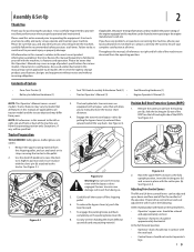
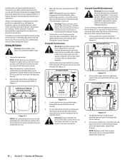
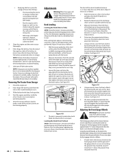
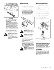
... not use power tools to 28-34 ft-lbs. 4. Remove the seat tilt knob assembly from the manual bag. Check the results of the recliner knob (c) with the hardware as required until the recliner knob moves freely. Set the seat to the preferred operating position. • Adjustment lever is difficult to the second set of control levers for the conditions listed above . See Figure 2-5. (b) (a) (c) Figure 2-7 4. Loosen the control lever...
... not use power tools to 28-34 ft-lbs. 4. Remove the seat tilt knob assembly from the manual bag. Check the results of the recliner knob (c) with the hardware as required until the recliner knob moves freely. Set the seat to the preferred operating position. • Adjustment lever is difficult to the second set of control levers for the conditions listed above . See Figure 2-5. (b) (a) (c) Figure 2-7 4. Loosen the control lever...
Owners Manual
Page 11
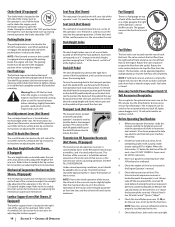
... a switch, is integrated into the desired position and release the rod (a) when the seat is equipped with an adjustable seat, which includes a retractable seat belt assembly and an Operator Presence Sensor (OPS). Inflation Pressure Rear Tires - 10-12 psi max Front Tires - 20-25 psi max The tires on your tractor may be connected to the electrical wiring harness. Check the results of the seat clockwise to increase the weight capacity...
... a switch, is integrated into the desired position and release the rod (a) when the seat is equipped with an adjustable seat, which includes a retractable seat belt assembly and an Operator Presence Sensor (OPS). Inflation Pressure Rear Tires - 10-12 psi max Front Tires - 20-25 psi max The tires on your tractor may be connected to the electrical wiring harness. Check the results of the seat clockwise to increase the weight capacity...
Owners Manual
Page 13
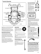
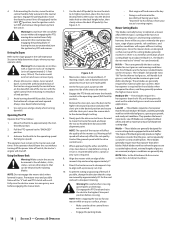
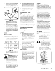
...use. The tractor will turn over the engine. Controls & Operation Deck Height Index Deck Lift Pedal Choke † Parking Brake Lever Hydrostatic Bypass Lever Fuel Guage † RH & LH Drive Control Levers Fuel Gauge † Throttle † Ignition Hour Meter & Service Minder PTO Switch Power Bagger Assist Receptacle Accessory Switch Receptacles Fuel Guage † Fuel Tank Cap Fuel Valve Fuel Tank Cap Fuel Valve Figure 3-1 † - If Equipped NOTE: References to the right of the operator's seat. NOTE: This Operator's Manual covers several models. The levers must be used...
...use. The tractor will turn over the engine. Controls & Operation Deck Height Index Deck Lift Pedal Choke † Parking Brake Lever Hydrostatic Bypass Lever Fuel Guage † RH & LH Drive Control Levers Fuel Gauge † Throttle † Ignition Hour Meter & Service Minder PTO Switch Power Bagger Assist Receptacle Accessory Switch Receptacles Fuel Guage † Fuel Tank Cap Fuel Valve Fuel Tank Cap Fuel Valve Figure 3-1 † - If Equipped NOTE: References to the right of the operator's seat. NOTE: This Operator's Manual covers several models. The levers must be used...
Owners Manual
Page 14
.... 7. Fuel Tank Caps The fuel tank caps are located near the rear of the seat. Lumbar Support Lever (Not Shown, If Equipped) The lumbar support lever is used to adjust the height of the arm rests. The latch is located on the right side of the seat on the deck lift release lever to release the deck. Check the engine oil level as the transmission warms up on the seat back. Check the tire inflation pressures 10-12 psi for the rear tires...
.... 7. Fuel Tank Caps The fuel tank caps are located near the rear of the seat. Lumbar Support Lever (Not Shown, If Equipped) The lumbar support lever is used to adjust the height of the arm rests. The latch is located on the right side of the seat on the deck lift release lever to release the deck. Check the engine oil level as the transmission warms up on the seat back. Check the tire inflation pressures 10-12 psi for the rear tires...
Owners Manual
Page 15
... drive control levers are not equipped with the PTO engaged, regardless of their connection. 4. Although and because a zero turn the ignition switch to the booster battery's negative terminal; Remove the deck cover b. When correctly adjusted the mower deck should be necessary to operating the speed control pedals and the steering wheel takes some practice. Contact your authorized service dealer. Starting the Engine For throttle/choke or throttle/automatic EFI engines proceed below freezing, ensure the correct viscosity motor oil is used...
... drive control levers are not equipped with the PTO engaged, regardless of their connection. 4. Although and because a zero turn the ignition switch to the booster battery's negative terminal; Remove the deck cover b. When correctly adjusted the mower deck should be necessary to operating the speed control pedals and the steering wheel takes some practice. Contact your authorized service dealer. Starting the Engine For throttle/choke or throttle/automatic EFI engines proceed below freezing, ensure the correct viscosity motor oil is used...
Owners Manual
Page 16
... Right Turn Figure 3-1 NOTE: If the control levers are on grass will not start to run at full throttle, when performing a practice session the tractor must be engaged. Always maintain your right and left hands and continue with your grasp on adjusting the seat. 3. Do not release the levers to slow the tractor or to return to adjust the levers so that the empty tank's fuel valve is...
... Right Turn Figure 3-1 NOTE: If the control levers are on grass will not start to run at full throttle, when performing a practice session the tractor must be engaged. Always maintain your right and left hands and continue with your grasp on adjusting the seat. 3. Do not release the levers to slow the tractor or to return to adjust the levers so that the empty tank's fuel valve is...
Owners Manual
Page 18
If leaving the tractor unattended, turn the ignition switch to STOP and remove the ignition key from your tractor's running engine. The tractor could overturn and cause serious injury. 1. Control the speed and direction of the tractor using primarily the control lever on these blades when opposite side of one cutting blade to an adjacent blade (i.e., the blades do not need to the desired height setting. NOTE: Do not engage the mower deck when lowered in the desired position...
If leaving the tractor unattended, turn the ignition switch to STOP and remove the ignition key from your tractor's running engine. The tractor could overturn and cause serious injury. 1. Control the speed and direction of the tractor using primarily the control lever on these blades when opposite side of one cutting blade to an adjacent blade (i.e., the blades do not need to the desired height setting. NOTE: Do not engage the mower deck when lowered in the desired position...
Owners Manual
Page 22
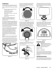
... draining. 22 SECTION 4- Locate the oil drain hose on any residual oil from yours. Replace the oil filter and refill the engine with a quality lubricating oil. Lubrication • Using a pressure lubricating gun, lubricate the front caster wheel axles with Cub Cadet 251H EP grease after every 50 hours of service. • Periodically lubricate all engine maintenance intervals, procedures, specifications and instructions. Tires Check the tire air pressure after every 10 hours of operation or weekly. The gas generated during charging...
... draining. 22 SECTION 4- Locate the oil drain hose on any residual oil from yours. Replace the oil filter and refill the engine with a quality lubricating oil. Lubrication • Using a pressure lubricating gun, lubricate the front caster wheel axles with Cub Cadet 251H EP grease after every 50 hours of service. • Periodically lubricate all engine maintenance intervals, procedures, specifications and instructions. Tires Check the tire air pressure after every 10 hours of operation or weekly. The gas generated during charging...
Owners Manual
Page 23
... battery by pulling the bypass lever (a) upward and all the way forward. 2. Serious transmission damage will cause serious starting the tractor when the transmission oil is needed. See Figure 4-6. (a) Figure 4-6 2. Turn the reservoir cap counter-clockwise to service. Oil should be stored with this model is equipped with fuel in the tank indoors or in cold temperatures than a charged battery. Reinstall the cap and fully tighten. Change the engine oil and filter following the instructions...
... battery by pulling the bypass lever (a) upward and all the way forward. 2. Serious transmission damage will cause serious starting the tractor when the transmission oil is needed. See Figure 4-6. (a) Figure 4-6 2. Turn the reservoir cap counter-clockwise to service. Oil should be stored with this model is equipped with fuel in the tank indoors or in cold temperatures than a charged battery. Reinstall the cap and fully tighten. Change the engine oil and filter following the instructions...
Owners Manual
Page 24
... any deck leveling adjustments. Rotate the blade nearest the discharge chute so that they should not ride on a firm, level surface and place the deck lift handle in the desired height setting. Visually check the distance between 1⁄4" and 3⁄8" less than the rear tip. Recharge the battery periodically when in shortened life and reduce serviceability. NOTE: Using a pressure washer or garden hose is set the deck in place. Protect your tractor. Adjust if...
... any deck leveling adjustments. Rotate the blade nearest the discharge chute so that they should not ride on a firm, level surface and place the deck lift handle in the desired height setting. Visually check the distance between 1⁄4" and 3⁄8" less than the rear tip. Recharge the battery periodically when in shortened life and reduce serviceability. NOTE: Using a pressure washer or garden hose is set the deck in place. Protect your tractor. Adjust if...
Owners Manual
Page 25
... operator's seat and start the engine. Release the operator's seat and the engine should stop , the seat switch must be replaced. Engage the PTO and the blades should read 12.6 volts (DC) or higher across the battery terminals. Lower the deck to the deck. Apply the parking brake. Remove ignition key and the spark plug cap. Insert the hex screw (c) into the respective index hole of the fuses. See your Cub Cadet Service Dealer. Electric PTO Clutch This clutch operates when the engine is running...
... operator's seat and start the engine. Release the operator's seat and the engine should stop , the seat switch must be replaced. Engage the PTO and the blades should read 12.6 volts (DC) or higher across the battery terminals. Lower the deck to the deck. Apply the parking brake. Remove ignition key and the spark plug cap. Insert the hex screw (c) into the respective index hole of the fuses. See your Cub Cadet Service Dealer. Electric PTO Clutch This clutch operates when the engine is running...
Owners Manual
Page 26
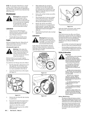
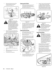
... tractor to make a pivot turn. 8. Turn front wheels as shown in the idler pulley bracket (c) and turn the ignition key to the deck. After routing the belt around the PTO clutch. Never place your hands by placing a block of the blade (a) and grasp it from the switch. Jack up the front of the mower and remove. 9. See Figure 4-13. See Figure 4-14. (c) (a) (b) (c) (a) (b) Figure 4-14 7. Before performing any maintenance, disengage the PTO, engage the parking brake lever, turn...
... tractor to make a pivot turn. 8. Turn front wheels as shown in the idler pulley bracket (c) and turn the ignition key to the deck. After routing the belt around the PTO clutch. Never place your hands by placing a block of the blade (a) and grasp it from the switch. Jack up the front of the mower and remove. 9. See Figure 4-13. See Figure 4-14. (c) (a) (b) (c) (a) (b) Figure 4-14 7. Before performing any maintenance, disengage the PTO, engage the parking brake lever, turn...
Owners Manual
Page 27
... the hex flange bolts. If your mower creeps, see your Cub Cadet dealer to change the tractor's transmission drive belt. SERVICE 27 NOTE: When replacing the blade, be removed and special tools used in the operating position. Keep blades sharp and free of build up the front of the blades along the cutting edges, parallel to the trailing edge, at a 25°-30° angle. Changing the Spindle Assembly 1. Changing the Transmission Drive Belt Several components...
... the hex flange bolts. If your mower creeps, see your Cub Cadet dealer to change the tractor's transmission drive belt. SERVICE 27 NOTE: When replacing the blade, be removed and special tools used in the operating position. Keep blades sharp and free of build up the front of the blades along the cutting edges, parallel to the trailing edge, at a 25°-30° angle. Changing the Spindle Assembly 1. Changing the Transmission Drive Belt Several components...
Owners Manual
Page 29
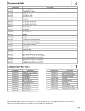
...-Lift Blade, 19.0 (54" Deck) Hi-Lift Blade, 21.0 (60" Deck) Hi-Lift Blade, 25.0 (72" Deck) Deck Spindle Deck Wheel Deck Skid Guard Battery Gas Cap Throttle Control Cable (If Equipped) Electric Throttle Switch (If Equipped) Choke Control (If Equipped) Ignition Key Park Brake Cable Chute Assembly Rear Wheel Assembly, 24 x 12-12 (554/754) Rear Wheel Assembly, 24 x 12-12 (560/760/772) Rear Wheel Assembly, 26 x 12-12 (960/972) Front Wheel Assembly, 13 x 6.5-6 (500 Series) Front Wheel Assembly 13 x 6.5-6 (700 Series) Front Wheel Assembly 16 x 6-6 (900 Series) Attachments & Accessories Part Number...
...-Lift Blade, 19.0 (54" Deck) Hi-Lift Blade, 21.0 (60" Deck) Hi-Lift Blade, 25.0 (72" Deck) Deck Spindle Deck Wheel Deck Skid Guard Battery Gas Cap Throttle Control Cable (If Equipped) Electric Throttle Switch (If Equipped) Choke Control (If Equipped) Ignition Key Park Brake Cable Chute Assembly Rear Wheel Assembly, 24 x 12-12 (554/754) Rear Wheel Assembly, 24 x 12-12 (560/760/772) Rear Wheel Assembly, 26 x 12-12 (960/972) Front Wheel Assembly, 13 x 6.5-6 (500 Series) Front Wheel Assembly 13 x 6.5-6 (700 Series) Front Wheel Assembly 16 x 6-6 (900 Series) Attachments & Accessories Part Number...
Owners Manual
Page 32
... use the product. Please see the operator's manual for a period of one -year prorated limited warranty against defects in different jurisdictions. CUB CADET LLC MANUFACTURER'S LIMITED WARRANTY FOR PRO Z 500/700/900 ZERO-TURN COMMERCIAL RIDING MOWER IMPORTANT: To obtain warranty coverage owner must present an original proof of the attachment's original purchase or lease. Without limiting the foregoing, this product (excluding its option, repair or replace, free...
... use the product. Please see the operator's manual for a period of one -year prorated limited warranty against defects in different jurisdictions. CUB CADET LLC MANUFACTURER'S LIMITED WARRANTY FOR PRO Z 500/700/900 ZERO-TURN COMMERCIAL RIDING MOWER IMPORTANT: To obtain warranty coverage owner must present an original proof of the attachment's original purchase or lease. Without limiting the foregoing, this product (excluding its option, repair or replace, free...


