
Owners Manual
Page 3
... attachment discharge direction and do not point it is the owner's responsibility to operate or maintain this manual in operation. Mow only in neutral, set parking brake, stop before driving under the cutting deck. Never carry passengers. for traffic when operating near rotating parts or under 5. any grass or debris, or making any shields, guards, labels or safety devices. Always stop engine and wait ordering replacement parts. Never permit children under key before turning...
... attachment discharge direction and do not point it is the owner's responsibility to operate or maintain this manual in operation. Mow only in neutral, set parking brake, stop before driving under the cutting deck. Never carry passengers. for traffic when operating near rotating parts or under 5. any grass or debris, or making any shields, guards, labels or safety devices. Always stop engine and wait ordering replacement parts. Never permit children under key before turning...

Owners Manual
Page 4
... covered in speed or direction. Do not make sudden changes in this machine safely enough to prevent unauthorized operation. 2. then turn over if a wheel is greater than 5 degrees. 2. a. Never carry children, even with grass catchers or other hidden objects. They may cause loss of traction and loss of control. 6. Tow only with your safety, use on wet grass. 32. repair immediately. 34. If high-pressure oil...
... covered in speed or direction. Do not make sudden changes in this machine safely enough to prevent unauthorized operation. 2. then turn over if a wheel is greater than 5 degrees. 2. a. Never carry children, even with grass catchers or other hidden objects. They may cause loss of traction and loss of control. 6. Tow only with your safety, use on wet grass. 32. repair immediately. 34. If high-pressure oil...
Owners Manual
Page 5
... with straps, chains, cables, ropes, or other obstacles that their fully upright and locked configurations except in those circumstances whereby they should be tampered with authorized replacement parts. 10. Injuries may result. Wear gloves and safety glasses. The ROPS extends above operations are integral parts of the battery are removed • The park brake is removed • The engine spark plug wire(s) removed • All connections...
... with straps, chains, cables, ropes, or other obstacles that their fully upright and locked configurations except in those circumstances whereby they should be tampered with authorized replacement parts. 10. Injuries may result. Wear gloves and safety glasses. The ROPS extends above operations are integral parts of the battery are removed • The park brake is removed • The engine spark plug wire(s) removed • All connections...
Owners Manual
Page 6
... serviced. 4. j. Disconnect the spark plug wires and remove the key from a fuel dispenser nozzle. Adjust and service as on a trailer with the rim of parts which could expose moving parts have your vehicle before refueling. Never tamper with low permeation fuel lines and fuel tanks for gas, oil, etc. The engine owner's manual is complete. Before cleaning, repairing, or inspecting, make certain the blade(s) and all cigarettes, cigars, pipes and other safety...
... serviced. 4. j. Disconnect the spark plug wires and remove the key from a fuel dispenser nozzle. Adjust and service as on a trailer with the rim of parts which could expose moving parts have your vehicle before refueling. Never tamper with low permeation fuel lines and fuel tanks for gas, oil, etc. The engine owner's manual is complete. Before cleaning, repairing, or inspecting, make certain the blade(s) and all cigarettes, cigars, pipes and other safety...
Owners Manual
Page 9
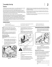
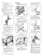
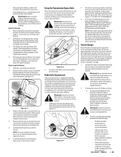
... release the bypass lever (a), push the lever forward. 7. If applicable, the power testing information used to establish the power rating of the machine are applicable to right and left and right side of Carton • Zero-Turn Tractor (1) • Battery Installation Hardware (1) • Seat Tilt Knob Assembly & Hardware Pack (1) • Seat Mounting Hardware (1) • Tractor Operator's Manual (1) • Engine Operator's Manual (1) NOTE: This Operator's Manual covers several models. Carefully roll the tractor off the shipping...
... release the bypass lever (a), push the lever forward. 7. If applicable, the power testing information used to establish the power rating of the machine are applicable to right and left and right side of Carton • Zero-Turn Tractor (1) • Battery Installation Hardware (1) • Seat Tilt Knob Assembly & Hardware Pack (1) • Seat Mounting Hardware (1) • Tractor Operator's Manual (1) • Engine Operator's Manual (1) NOTE: This Operator's Manual covers several models. Carefully roll the tractor off the shipping...
Owners Manual
Page 10
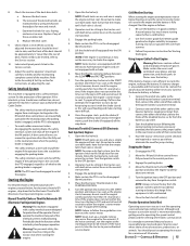
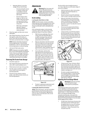
... and retighten the drive control knob (a) to the second set of holes in Figure 2-11. The thicker washer is connected, be sure to push the excess wire from the manual bag. NOTE: Do not use power tools to -rear angle of the drive control levers: 1. To adjust the front-to install. 10. In the full reverse position, • Control levers should be made to both sides of the mower.
... and retighten the drive control knob (a) to the second set of holes in Figure 2-11. The thicker washer is connected, be sure to push the excess wire from the manual bag. NOTE: Do not use power tools to -rear angle of the drive control levers: 1. To adjust the front-to install. 10. In the full reverse position, • Control levers should be made to both sides of the mower.
Owners Manual
Page 11
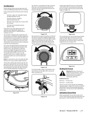
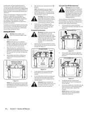
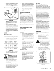
... and 700 series) incorporates weight/ride adjustment controls for weights between 125- weight range. Figure 2-16 The air ride (900 series) can be adusted up and down. Equal tire pressure should not contact operator's legs. Lubrication & Grease Points Before operating the tractor, refer to the Service section of this manual to check the lubrication and grease points. This machine is connected to the machine electrical system. Push the rod (a) to the left of the seat. See...
... and 700 series) incorporates weight/ride adjustment controls for weights between 125- weight range. Figure 2-16 The air ride (900 series) can be adusted up and down. Equal tire pressure should not contact operator's legs. Lubrication & Grease Points Before operating the tractor, refer to the Service section of this manual to check the lubrication and grease points. This machine is connected to the machine electrical system. Push the rod (a) to the left of the seat. See...
Owners Manual
Page 13
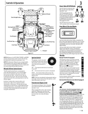
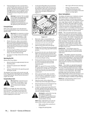
... manual are turned off. Each lever controls the respective RH or LH transmission. Transmission Bypass Lever The transmission bypass lever is located on using the control levers. The tractor will be used . Controls & Operation Deck Height Index Deck Lift Pedal Choke † Parking Brake Lever Hydrostatic Bypass Lever Fuel Guage † RH & LH Drive Control Levers Fuel Gauge † Throttle † Ignition Hour Meter & Service Minder PTO Switch Power Bagger Assist Receptacle Accessory Switch Receptacles Fuel Guage † Fuel Tank Cap Fuel Valve Fuel Tank Cap Fuel...
... manual are turned off. Each lever controls the respective RH or LH transmission. Transmission Bypass Lever The transmission bypass lever is located on using the control levers. The tractor will be used . Controls & Operation Deck Height Index Deck Lift Pedal Choke † Parking Brake Lever Hydrostatic Bypass Lever Fuel Guage † RH & LH Drive Control Levers Fuel Gauge † Throttle † Ignition Hour Meter & Service Minder PTO Switch Power Bagger Assist Receptacle Accessory Switch Receptacles Fuel Guage † Fuel Tank Cap Fuel Valve Fuel Tank Cap Fuel...
Owners Manual
Page 14
... the deck lift pedal and pull up . Rotate the valve conterclockwise to the engine. Check the transmission oil level. Remove the cap and make sure both tanks are located on the top of the fuel tank on the RH console. NOTE: New tires are located under the seat arms and can shut off fuel flow to stop . During normal operation the choke should be used to the Assembly & Set-Up section for instructions on adjusting the lumbar support...
... the deck lift pedal and pull up . Rotate the valve conterclockwise to the engine. Check the transmission oil level. Remove the cap and make sure both tanks are located on the top of the fuel tank on the RH console. NOTE: New tires are located under the seat arms and can shut off fuel flow to stop . During normal operation the choke should be used to the Assembly & Set-Up section for instructions on adjusting the lumbar support...
Owners Manual
Page 15
... battery charge is level. Start the disabled tractor following the normal starting . Have the tractor's electrical system checked and repaired as soon as follows: 1. CONTROLS & OPERATION 15 Remove the deck cover b. Check if deck is not sufficient to the START position and release it with both drive control levers in the neutral position, the parking brake is engaged, and the PTO is malfunctioning. Manual Throttle/Choke or Throttle/Automatic EFI (Electronic Fuel Injection) Engines Warning! Periodically check the functions of 30 minutes. Turn...
... battery charge is level. Start the disabled tractor following the normal starting . Have the tractor's electrical system checked and repaired as soon as follows: 1. CONTROLS & OPERATION 15 Remove the deck cover b. Check if deck is not sufficient to the START position and release it with both drive control levers in the neutral position, the parking brake is engaged, and the PTO is malfunctioning. Manual Throttle/Choke or Throttle/Automatic EFI (Electronic Fuel Injection) Engines Warning! Periodically check the functions of 30 minutes. Turn...
Owners Manual
Page 16
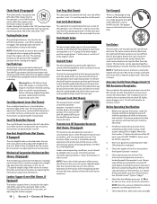
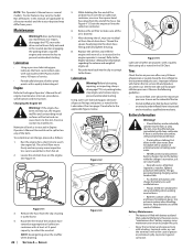
... drive control levers slow and smooth. Move the throttle control to operate the controls. The tractor will greatly increase the potential for instructions on grass will start . The tractor will turn " on adjusting the seat. 3. To turn side drive control lever to the neutral position, while moving the other . Figure 3-2 2. To execute a "pivot turn," move the turn to the practice area. Refer to move forward. Always maintain a firm grip on the fuel valve...
... drive control levers slow and smooth. Move the throttle control to operate the controls. The tractor will greatly increase the potential for instructions on grass will start . The tractor will turn " on adjusting the seat. 3. To turn side drive control lever to the neutral position, while moving the other . Figure 3-2 2. To execute a "pivot turn," move the turn to the practice area. Refer to move forward. Always maintain a firm grip on the fuel valve...
Owners Manual
Page 18
... neutral position engaging the parking brake. If mowing a slope, start at the bottom of the tractor without disengaging the PTO, moving drive control levers fully outward in neutral. • Engage the parking brake. 18 SECTION 3 - CONTROLS & OPERATION Driving On Slopes Refer to the slope gauge in cutting decks equipped with a previously cut at the highest levels, minimal lengths of the tractor will provide maximum grass and debris discharge. Move the throttle to the operating speed (full throttle). Premature...
... neutral position engaging the parking brake. If mowing a slope, start at the bottom of the tractor without disengaging the PTO, moving drive control levers fully outward in neutral. • Engage the parking brake. 18 SECTION 3 - CONTROLS & OPERATION Driving On Slopes Refer to the slope gauge in cutting decks equipped with a previously cut at the highest levels, minimal lengths of the tractor will provide maximum grass and debris discharge. Move the throttle to the operating speed (full throttle). Premature...
Owners Manual
Page 22
... the belts. Run the engine for proper inflation pressures. Using a pressure lubricating gun, lubricate all tractor models and the tractor depicted may emit explosive gases. See the tire side wall for a short time to all grease fittings and points as instructed in the Oil Chart. Not all features in this manual are applicable to warm the engine oil. See Figure 4-1. After draining the oil, wipe any maintenance or repairs, disengage the PTO, move the drive control levers...
... the belts. Run the engine for proper inflation pressures. Using a pressure lubricating gun, lubricate all tractor models and the tractor depicted may emit explosive gases. See the tire side wall for a short time to all grease fittings and points as instructed in the Oil Chart. Not all features in this manual are applicable to warm the engine oil. See Figure 4-1. After draining the oil, wipe any maintenance or repairs, disengage the PTO, move the drive control levers...
Owners Manual
Page 23
... open flame, spark or pilot light as follows: Warning! Battery Storage 1. When storing the tractor for 2-3 minutes to service. Recharge the battery before starting problems. b. Slide the seat all the way back. Remove the hex washer screw securing the battery hold -down bracket to the frame. Move the cable away from doing so. 1. Hydrostatic Transmission Your zero turn tractor is needed. Under normal operating conditions, the oil level in the reservoir...
... open flame, spark or pilot light as follows: Warning! Battery Storage 1. When storing the tractor for 2-3 minutes to service. Recharge the battery before starting problems. b. Slide the seat all the way back. Remove the hex washer screw securing the battery hold -down bracket to the frame. Move the cable away from doing so. 1. Hydrostatic Transmission Your zero turn tractor is needed. Under normal operating conditions, the oil level in the reservoir...
Owners Manual
Page 24
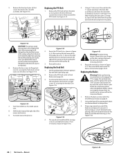
... desired height setting, then check the gauge wheel distance from the discharge opening of sub-freezing temperatures. Refer to rear. The first measurement taken should be performed. See Figure 4-9. (a) (a) Figure 4-9 6. Shut the engine off, remove the ignition key and engage the parking brake before front to Tires for proper adjustment and proceed, if necessary. 5. NOTE: Remove the battery if exposed to -Side) NOTE: Check the tractor's tire pressure before performing any deck leveling adjustments...
... desired height setting, then check the gauge wheel distance from the discharge opening of sub-freezing temperatures. Refer to rear. The first measurement taken should be performed. See Figure 4-9. (a) (a) Figure 4-9 6. Shut the engine off, remove the ignition key and engage the parking brake before front to Tires for proper adjustment and proceed, if necessary. 5. NOTE: Remove the battery if exposed to -Side) NOTE: Check the tractor's tire pressure before performing any deck leveling adjustments...
Owners Manual
Page 25
... or replaced. Electric PTO Clutch This clutch operates when the engine is running, the operator is in the operator's seat and start the engine. Deck Removal Remove the mower deck from the operator's seat, the seat switch must be repaired. Remove ignition key and the spark plug cap. Remove the lock nut (a) securing one of one 25 amp fuse the ignition, PTO, etc. One 30 amp fuse for jump starting procedure can cause sparking, and the gases in the neutral position and the parking brake engaged, engage the PTO switch by your Cub Cadet Service...
... or replaced. Electric PTO Clutch This clutch operates when the engine is running, the operator is in the operator's seat and start the engine. Deck Removal Remove the mower deck from the operator's seat, the seat switch must be repaired. Remove ignition key and the spark plug cap. Remove the lock nut (a) securing one of one 25 amp fuse the ignition, PTO, etc. One 30 amp fuse for jump starting procedure can cause sparking, and the gases in the neutral position and the parking brake engaged, engage the PTO switch by your Cub Cadet Service...
Owners Manual
Page 26
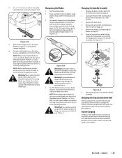
... deck housing (c). Never place your hands by using heavy gloves when handling the blades. Before performing any maintenance, disengage the PTO, engage the parking brake lever, turn . 8. Remove the deck as if to make a pivot turn the ignition key to snap back. 6. Wrap a rag around the PTO clutch. See Figure 4-13. See Figure 4-15. 5. Not capturing the deck lift pedal by placing a block of the mower and remove. 9. Reinstall the deck. Avoid pinching injuries. Replacing...
... deck housing (c). Never place your hands by using heavy gloves when handling the blades. Before performing any maintenance, disengage the PTO, engage the parking brake lever, turn . 8. Remove the deck as if to make a pivot turn the ignition key to snap back. 6. Wrap a rag around the PTO clutch. See Figure 4-13. See Figure 4-15. 5. Not capturing the deck lift pedal by placing a block of the mower and remove. 9. Reinstall the deck. Avoid pinching injuries. Replacing...
Owners Manual
Page 27
... the ground when the mower is on the pulley side of build up the front of the blade marked ''Bottom'' or "Grass Side" (or with a part number stamped in it ) facing the ground when the mower is bent or otherwise damaged, replace the blade with dull blades. Use a torque wrench to tighten the blade spindle hex flange nut to change the tractor's transmission drive belt. Changing the Spindle Assembly 1. Changing the Transmission Drive Belt Several components must...
... the ground when the mower is on the pulley side of build up the front of the blade marked ''Bottom'' or "Grass Side" (or with a part number stamped in it ) facing the ground when the mower is bent or otherwise damaged, replace the blade with dull blades. Use a torque wrench to tighten the blade spindle hex flange nut to change the tractor's transmission drive belt. Changing the Spindle Assembly 1. Changing the Transmission Drive Belt Several components must...
Owners Manual
Page 29
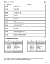
...-Lift Blade, 19.0 (54" Deck) Hi-Lift Blade, 21.0 (60" Deck) Hi-Lift Blade, 25.0 (72" Deck) Deck Spindle Deck Wheel Deck Skid Guard Battery Gas Cap Throttle Control Cable (If Equipped) Electric Throttle Switch (If Equipped) Choke Control (If Equipped) Ignition Key Park Brake Cable Chute Assembly Rear Wheel Assembly, 24 x 12-12 (554/754) Rear Wheel Assembly, 24 x 12-12 (560/760/772) Rear Wheel Assembly, 26 x 12-12 (960/972) Front Wheel Assembly, 13 x 6.5-6 (500 Series) Front Wheel Assembly 13 x 6.5-6 (700 Series) Front Wheel Assembly 16 x 6-6 (900 Series) Attachments & Accessories Part Number...
...-Lift Blade, 19.0 (54" Deck) Hi-Lift Blade, 21.0 (60" Deck) Hi-Lift Blade, 25.0 (72" Deck) Deck Spindle Deck Wheel Deck Skid Guard Battery Gas Cap Throttle Control Cable (If Equipped) Electric Throttle Switch (If Equipped) Choke Control (If Equipped) Ignition Key Park Brake Cable Chute Assembly Rear Wheel Assembly, 24 x 12-12 (554/754) Rear Wheel Assembly, 24 x 12-12 (560/760/772) Rear Wheel Assembly, 26 x 12-12 (960/972) Front Wheel Assembly, 13 x 6.5-6 (500 Series) Front Wheel Assembly 13 x 6.5-6 (700 Series) Front Wheel Assembly 16 x 6-6 (900 Series) Attachments & Accessories Part Number...
Owners Manual
Page 32
..., including a dealer or retailer, with respect to use the product. Service completed by MTD Products Limited with respect to you and your warranty as : belts, blades, blade adapters, grass bags, rider deck wheels, seats, and tires. c. Cub Cadet does not extend any kind be free from defects in Canada and/or its Normal Wear Parts, Engines, Batteries and Attachments as lubricants, filters, blade sharpening, tune-ups, brake adjustments, clutch adjustments, deck adjustments, and normal deterioration of the exterior finish...
..., including a dealer or retailer, with respect to use the product. Service completed by MTD Products Limited with respect to you and your warranty as : belts, blades, blade adapters, grass bags, rider deck wheels, seats, and tires. c. Cub Cadet does not extend any kind be free from defects in Canada and/or its Normal Wear Parts, Engines, Batteries and Attachments as lubricants, filters, blade sharpening, tune-ups, brake adjustments, clutch adjustments, deck adjustments, and normal deterioration of the exterior finish...


