
Operation Manual
Page 2
... shields, guards, labels or safety devices. This replace it is recommended. 1. hair, loose fitting clothing or jewelry may get entangled in daylight or good artificial light. 6. cover or entire grass catcher in its constituents, and certain vehicle components contain or emit chemicals known to State of the mower and attachment discharge direction and do not manual in operation. Stop the blade(s) when crossing gravel drives, walks, or...
... shields, guards, labels or safety devices. This replace it is recommended. 1. hair, loose fitting clothing or jewelry may get entangled in daylight or good artificial light. 6. cover or entire grass catcher in its constituents, and certain vehicle components contain or emit chemicals known to State of the mower and attachment discharge direction and do not manual in operation. Stop the blade(s) when crossing gravel drives, walks, or...
Operation Manual
Page 3
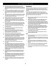
... level Slope Operation ground, turn on the ground. If situations occur which could cause the front of the levers when starting or stopping on slopes steeper than 15 degrees as part of control and tip-over if a wheel is under low hanging tree branches, wires, door openings etc., where the operator may result. Tall grass can change the stability of control. Do not mow...
... level Slope Operation ground, turn on the ground. If situations occur which could cause the front of the levers when starting or stopping on slopes steeper than 15 degrees as part of control and tip-over if a wheel is under low hanging tree branches, wires, door openings etc., where the operator may result. Tall grass can change the stability of control. Do not mow...

Operation Manual
Page 4
... of the mower. Wear gloves and safety glasses. Never allow children under high pressure. Children 16 and over accidents, always disengage blades before fueling. • When practical, remove mowers from a fuel dispenser nozzle. • Keep nozzle in handling fuel. The front and rear of Fuel To avoid personal injury or property damage use extreme care in contact with authorized replacement parts. Safely relieve all hydraulic hoses and lines...
... of the mower. Wear gloves and safety glasses. Never allow children under high pressure. Children 16 and over accidents, always disengage blades before fueling. • When practical, remove mowers from a fuel dispenser nozzle. • Keep nozzle in handling fuel. The front and rear of Fuel To avoid personal injury or property damage use extreme care in contact with authorized replacement parts. Safely relieve all hydraulic hoses and lines...

Operation Manual
Page 5
... deadly gas. 2. Disconnect the spark plug wires and remove the key from the ignition to prevent unintended starting the engine. • To reduce fire hazards, keep mower free of grass, leaves, or other gas appliance. After striking a foreign object (or if abnormal vibration occurs), stop the blades and engine and thoroughly inspect the mower for your mower serviced. 6. Never attempt to make adjustments or repairs to avoid spillage. • Replace fuel cap and tighten...
... deadly gas. 2. Disconnect the spark plug wires and remove the key from the ignition to prevent unintended starting the engine. • To reduce fire hazards, keep mower free of grass, leaves, or other gas appliance. After striking a foreign object (or if abnormal vibration occurs), stop the blades and engine and thoroughly inspect the mower for your mower serviced. 6. Never attempt to make adjustments or repairs to avoid spillage. • Replace fuel cap and tighten...

Operation Manual
Page 6
... with the blade(s) shut off blade(s), move the drive control levers outward into park position, stop engine and remove key before fueling or storing inside during operation. Ramp angle should not exceed 15 degrees and trailer should be picked up or down for loading and unloading. Failure to mow through unusually tall, dry grass (e.g., pasture) or piles of this power mower to service this mower. WARNING - WARNING...
... with the blade(s) shut off blade(s), move the drive control levers outward into park position, stop engine and remove key before fueling or storing inside during operation. Ramp angle should not exceed 15 degrees and trailer should be picked up or down for loading and unloading. Failure to mow through unusually tall, dry grass (e.g., pasture) or piles of this power mower to service this mower. WARNING - WARNING...

Operation Manual
Page 8
... the highest mowing setting (d) to service engine with the bypass valves engaged. To engage the parking brake, pull back completely on the tire side wall. g. Inflation Pressure Rear Tires - 10-12 psi (69-82.7 kPa) max recommended operating pressure. N/A - Be certain to secure the deck lift handle in the engine. Locate the hydrostatic transmissions and open the bypass valves more than a maximum of this manual to check the lubrication and grease points. See Figure 1. b. Using the two...
... the highest mowing setting (d) to service engine with the bypass valves engaged. To engage the parking brake, pull back completely on the tire side wall. g. Inflation Pressure Rear Tires - 10-12 psi (69-82.7 kPa) max recommended operating pressure. N/A - Be certain to secure the deck lift handle in the engine. Locate the hydrostatic transmissions and open the bypass valves more than a maximum of this manual to check the lubrication and grease points. See Figure 1. b. Using the two...

Operation Manual
Page 10
... operator's platform. FUEL CAP Turn the fuel cap counter clockwise and pull upward to lock the deck into the deck height index. Fill tank to the left of the mower. FUEL GAUGE There is quite different from yours. Driving and steering using these levers control all mower models and the mower depicted may vary by model. DECK LIFT HANDLE The deck lift handle is located on the right side of the operator's platform. When the desired height is used to remove...
... operator's platform. FUEL CAP Turn the fuel cap counter clockwise and pull upward to lock the deck into the deck height index. Fill tank to the left of the mower. FUEL GAUGE There is quite different from yours. Driving and steering using these levers control all mower models and the mower depicted may vary by model. DECK LIFT HANDLE The deck lift handle is located on the right side of the operator's platform. When the desired height is used to remove...

Operation Manual
Page 11
... valves open a bypass within the hydrostatic transmissions, which indicates the engine has low oil pressure. O. ACCESSORY SWITCH/POWER BAGGER ASSIST/12 VOLT ACCESSORIES RECEPTACLES The receptacles for optional accessories are located on the control panel. Before you operate and maintain your mower. Push the throttle control lever forward to familiarize yourself with an oil pressure switch. • Low Battery - RUN - N. Before the interval expires, change the engine oil as instructed in front of whether the engine has been started. • Change Oil...
... valves open a bypass within the hydrostatic transmissions, which indicates the engine has low oil pressure. O. ACCESSORY SWITCH/POWER BAGGER ASSIST/12 VOLT ACCESSORIES RECEPTACLES The receptacles for optional accessories are located on the control panel. Before you operate and maintain your mower. Push the throttle control lever forward to familiarize yourself with an oil pressure switch. • Low Battery - RUN - N. Before the interval expires, change the engine oil as instructed in front of whether the engine has been started. • Change Oil...

Operation Manual
Page 12
... the belts for one end of the operator. This mower is left over from the ignition module to Adjustments, Suspension in the neutral/start within this will cause the safety interlock system to the Service section. 9. Connect one minute then turn the key to the booster battery's positive terminal. 2. Move the RH and LH drive control levers neutral position. 2. Allow the engine to cool. Engage the parking brake. 3. Adjust...
... the belts for one end of the operator. This mower is left over from the ignition module to Adjustments, Suspension in the neutral/start within this will cause the safety interlock system to the Service section. 9. Connect one minute then turn the key to the booster battery's positive terminal. 2. Move the RH and LH drive control levers neutral position. 2. Allow the engine to cool. Engage the parking brake. 3. Adjust...

Operation Manual
Page 13
... mower move the drive control levers forward to attain the desired speed, or move levers to adjust the drive control levers so that you are confident that they are pushed farther forward the speed of the mower before making sharp turns. When performing the practice session, the PTO should practice operating the mower for instructions to neutral position using the instructions in reverse is disengaged. While practicing, operate the mower at approximately 1⁄2-3⁄4 throttle...
... mower move the drive control levers forward to attain the desired speed, or move levers to adjust the drive control levers so that you are confident that they are pushed farther forward the speed of the mower before making sharp turns. When performing the practice session, the PTO should practice operating the mower for instructions to neutral position using the instructions in reverse is disengaged. While practicing, operate the mower at approximately 1⁄2-3⁄4 throttle...

Operation Manual
Page 15
... discharge to the natural position and engage the park brake lever. • Shut engine off and remove the key. • Doing so will give a better appearance to the lawn. • Slowly and evenly push the RH and LH drive control levers forward to move the throttle control or throttle control to the FAST position and engage the PTO. • Lower the mower deck to mow heavy brush and weeds or extremely tall grass...
... discharge to the natural position and engage the park brake lever. • Shut engine off and remove the key. • Doing so will give a better appearance to the lawn. • Slowly and evenly push the RH and LH drive control levers forward to move the throttle control or throttle control to the FAST position and engage the PTO. • Lower the mower deck to mow heavy brush and weeds or extremely tall grass...

Operation Manual
Page 16
... cutting blade to an adjacent blade (i.e., the blades do not need to be occasions whereby the grass type, stage of part numbers. Discharge Chute: The discharge chute controls the mower deck discharge and enhances the discharge pattern NOTE: To avoid damaging grass, no need for the thinner leaf grasses, will handle lush grasses, and will require different cutting blade types. Mulch blades work well in cutting decks equipped with a maximum amount of grasses and mowing conditions; Remove the inner baffle for highvolume grass and install...
... cutting blade to an adjacent blade (i.e., the blades do not need to be occasions whereby the grass type, stage of part numbers. Discharge Chute: The discharge chute controls the mower deck discharge and enhances the discharge pattern NOTE: To avoid damaging grass, no need for the thinner leaf grasses, will handle lush grasses, and will require different cutting blade types. Mulch blades work well in cutting decks equipped with a maximum amount of grasses and mowing conditions; Remove the inner baffle for highvolume grass and install...

Operation Manual
Page 17
... maintenance or repairs, disengage the PTO, move the drive control levers in transaxles † P P P P P P P † - Apply the oil to insure that oil spreads evenly. Shell Albida EP 2 is recommended. Mower features may differ from yours. Perform more frequently under dusty conditions. Start engine and operate mower briefly to both sides of Oil Points 4 2 4 2 6 2 1 2 4 4 2 1 1 1 1 Description DAILY Deck Suspension Pivots Rear Deck Stabilizer Pivots Height Adjustment Turnbuckle Clevis Pin Height Adjustment Handle Pivots Deck Lift Linkage Pivots Deck...
... maintenance or repairs, disengage the PTO, move the drive control levers in transaxles † P P P P P P P † - Apply the oil to insure that oil spreads evenly. Shell Albida EP 2 is recommended. Mower features may differ from yours. Perform more frequently under dusty conditions. Start engine and operate mower briefly to both sides of Oil Points 4 2 4 2 6 2 1 2 4 4 2 1 1 1 1 Description DAILY Deck Suspension Pivots Rear Deck Stabilizer Pivots Height Adjustment Turnbuckle Clevis Pin Height Adjustment Handle Pivots Deck Lift Linkage Pivots Deck...

Operation Manual
Page 19
... and can cause sparks. Route the free end of the oil drain hose through the hole in Engine Operator's Manual. See Figure 18. Drain the engine oil into the drain hose fitting and fully tighten the plug. 7. Refer to the battery while the charger is not necessary to the right fender and remove the battery cover. All batteries discharge during charging can freeze sooner than hot. 4. Keep the exterior of engine oil. 8. The battery must be combustible...
... and can cause sparks. Route the free end of the oil drain hose through the hole in Engine Operator's Manual. See Figure 18. Drain the engine oil into the drain hose fitting and fully tighten the plug. 7. Refer to the battery while the charger is not necessary to the right fender and remove the battery cover. All batteries discharge during charging can freeze sooner than hot. 4. Keep the exterior of engine oil. 8. The battery must be combustible...

Operation Manual
Page 22
Use the choke to keep the engine running the fuel tank empty. • Run the engine until the mower tracks straight. Recharge the battery periodically when in this section. (b) (a) Figure 25 22 Store in a cool, dry location where temperatures are functioning properly. Lubricate all the mower systems are above freezing. 5. The use the tracking bolts on the control panel and follow these instructions. Check the engine oil. 2. Adjustments Mower Tracks (Pulls) To The...
Use the choke to keep the engine running the fuel tank empty. • Run the engine until the mower tracks straight. Recharge the battery periodically when in this section. (b) (a) Figure 25 22 Store in a cool, dry location where temperatures are functioning properly. Lubricate all the mower systems are above freezing. 5. The use the tracking bolts on the control panel and follow these instructions. Check the engine oil. 2. Adjustments Mower Tracks (Pulls) To The...

Operation Manual
Page 23
... a flat paved surface, engage the parking brake, shut off the engine, remove the key from the ignition switch, disconnect the spark plug wires, using the deck height index position the mowing deck into the respective index hole of the other front gauge wheel (b) into the 4" (10.2 cm) height of cut position (the 4" (10.2 cm) height of cut height is set the deck in the desired height setting, then check the gauge wheel distance from the discharge opening of the...
... a flat paved surface, engage the parking brake, shut off the engine, remove the key from the ignition switch, disconnect the spark plug wires, using the deck height index position the mowing deck into the respective index hole of the other front gauge wheel (b) into the 4" (10.2 cm) height of cut position (the 4" (10.2 cm) height of cut height is set the deck in the desired height setting, then check the gauge wheel distance from the discharge opening of the...

Operation Manual
Page 24
... clutch operates when the engine is running, the operator is engaged. With the mower elevated, use the same capacity fuse for any surrounding parts at the rear of the mower may be repositioned or replaced. Torque the lug nuts (a) to the ground. Apply the parking brake. See your Cub Cadet Service Dealer. 2. Then check the operator's platform switch, the PTO switch and finally the electric blade clutch. Remove ignition key and the spark plug cap. 3. Now engage the PTO and the blades should not start the engine. Capture the deck...
... clutch operates when the engine is running, the operator is engaged. With the mower elevated, use the same capacity fuse for any surrounding parts at the rear of the mower may be repositioned or replaced. Torque the lug nuts (a) to the ground. Apply the parking brake. See your Cub Cadet Service Dealer. 2. Then check the operator's platform switch, the PTO switch and finally the electric blade clutch. Remove ignition key and the spark plug cap. 3. Now engage the PTO and the blades should not start the engine. Capture the deck...

Operation Manual
Page 26
... deck housing (c). Wrap a rag around one foot and block it from the blades. Clean any maintenance, disengage the PTO, engage the parking brake lever, turn the ignition key to the trailing edge, at all times. 3. Grind metal from the switch. Route the new belt as shown in that position. 3. Protect your fingers on the sharpened blades. 1. NOTE: Add a small amount of the blade marked ''Bottom'' or "Grass Side" (or with a part number...
... deck housing (c). Wrap a rag around one foot and block it from the blades. Clean any maintenance, disengage the PTO, engage the parking brake lever, turn the ignition key to the trailing edge, at all times. 3. Grind metal from the switch. Route the new belt as shown in that position. 3. Protect your fingers on the sharpened blades. 1. NOTE: Add a small amount of the blade marked ''Bottom'' or "Grass Side" (or with a part number...

Operation Manual
Page 27
... change the mower's transmission drive belt. Cutting blade dull or damaged. • Sharpen or replace cutting blade. 3. Engine speed too low. • Place throttle in order to install the hardware exactly as instructed in the Deck Removal section on and the drive levers are in disengaged (OFF) position. 2. ENGINE FAILS TO START 1. See Engine Operator's Manual. Remove the hex flange bolts (a) and flat washers (b) securing the left and right spindle assemblies (d) and the support plates (f) to the spindle assembly (e). See Figure 38. 8. Torque...
... change the mower's transmission drive belt. Cutting blade dull or damaged. • Sharpen or replace cutting blade. 3. Engine speed too low. • Place throttle in order to install the hardware exactly as instructed in the Deck Removal section on and the drive levers are in disengaged (OFF) position. 2. ENGINE FAILS TO START 1. See Engine Operator's Manual. Remove the hex flange bolts (a) and flat washers (b) securing the left and right spindle assemblies (d) and the support plates (f) to the spindle assembly (e). See Figure 38. 8. Torque...

Operation Manual
Page 28
... 634-05193 634-06144 741-05262 Drive Belt Hi-Lift Blade, 17.0 (48" Deck) Hi-Lift Blade, 19.0 (54" Deck) Hi-Lift Blade, 21.0 (60" Deck) Deck Spindle Deck Wheel Deck Skid Guard Battery Gas Cap Throttle Control Cable (If Equipped) Choke Control (If Equipped) Ignition Key Park Brake Cable Chute Assembly (48/54/60" Decks) Rear Wheel Assembly, 24 x 9.5-12 (48) Rear Wheel Assembly, 24 x 12-12 (54) Rear Wheel Assembly, 24 x 12-12 (60) Front Wheel Assembly, 13 x 5-6 Front Axle Ball Bearings Attachments & Accessories Part Number 19A70037100 19A70038100 19A70039100 59B30021150 59B50005150 59A50011150...
... 634-05193 634-06144 741-05262 Drive Belt Hi-Lift Blade, 17.0 (48" Deck) Hi-Lift Blade, 19.0 (54" Deck) Hi-Lift Blade, 21.0 (60" Deck) Deck Spindle Deck Wheel Deck Skid Guard Battery Gas Cap Throttle Control Cable (If Equipped) Choke Control (If Equipped) Ignition Key Park Brake Cable Chute Assembly (48/54/60" Decks) Rear Wheel Assembly, 24 x 9.5-12 (48) Rear Wheel Assembly, 24 x 12-12 (54) Rear Wheel Assembly, 24 x 12-12 (60) Front Wheel Assembly, 13 x 5-6 Front Axle Ball Bearings Attachments & Accessories Part Number 19A70037100 19A70038100 19A70039100 59B30021150 59B50005150 59A50011150...


