Jet Sweep Warranty Information
Page 1
... the risk and liability for rental expenses to temporarily replace a warranted product. BOX 361131 CLEVELAND, OHIO 44136-0019; KITCHENER, ON N2G 4J1; CUB CADET LLC MANUFACTURER'S LIMITED WARRANTY FOR SNOW THROWERS, LOG SPLITTERS, CHIPPER-SHREDDERS, CHIPPER-SHREDDER VACUUMS AND JET SWEEPS The limited warranty set forth in this manual will , at its option, repair...
... the risk and liability for rental expenses to temporarily replace a warranted product. BOX 361131 CLEVELAND, OHIO 44136-0019; KITCHENER, ON N2G 4J1; CUB CADET LLC MANUFACTURER'S LIMITED WARRANTY FOR SNOW THROWERS, LOG SPLITTERS, CHIPPER-SHREDDERS, CHIPPER-SHREDDER VACUUMS AND JET SWEEPS The limited warranty set forth in this manual will , at its option, repair...
500 Series Snow Throwers Brochure
Page 1
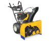
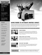
...don't waste time. innoVaTiVe FeaTureS For an incrediBLe eXPerience. 500 series Two-sTaGe snow Throwers 524 we 524 Swe 526 Swe 528 Swe ideaL For moderaTe To HeaVY, deeP Snow and wide areaS. 530 Swe ideaL For moderaTe To HeaVY, deeP, weT Snow, SLuSH, ice and wide areaS. Power sTeerinG Zero-Turn Posi-steer...or mar your driveway. You will spend less time in -DasH HeaDliGHT 4-WaY sinGle-HanD cHUTe conTrol 12" sTeel aUGer anD iMPeller cUB caDeT® oHV 4-cYcle enGine cool BlUe™ skiD sHoes 3-Year liMiTeD resiDenTial WarranTY† 1-Year liMiTeD coMMercial WarranTY† More Power...
...don't waste time. innoVaTiVe FeaTureS For an incrediBLe eXPerience. 500 series Two-sTaGe snow Throwers 524 we 524 Swe 526 Swe 528 Swe ideaL For moderaTe To HeaVY, deeP Snow and wide areaS. 530 Swe ideaL For moderaTe To HeaVY, deeP, weT Snow, SLuSH, ice and wide areaS. Power sTeerinG Zero-Turn Posi-steer...or mar your driveway. You will spend less time in -DasH HeaDliGHT 4-WaY sinGle-HanD cHUTe conTrol 12" sTeel aUGer anD iMPeller cUB caDeT® oHV 4-cYcle enGine cool BlUe™ skiD sHoes 3-Year liMiTeD resiDenTial WarranTY† 1-Year liMiTeD coMMercial WarranTY† More Power...
500 Series Snow Throwers Brochure
Page 2
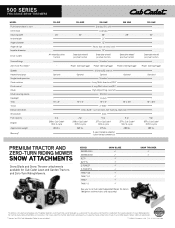
... 15" x 5" 2 qt. 208cc Cub Cadet® OHV 4-cycle 265 lbs. 524 SWE 24" Steerable wheel/ positive traction 526 swe Standard (110 volt) Extended 26" 21" 12" Heavy-duty serrated steel 12" Steerable wheel/ positive traction Standard 528 SWE 28" Steerable wheel/ positive traction Power .... 285 lbs. 3-year limited residential 1-year limited commercial 530 SWE 30" Steerable wheel/ positive traction Power steering/trigger Standard 16" x 6.5" 5 qt. 357cc Cub Cadet® OHV 4-cycle 285 lbs. 500 SERIES TWO-STAGE SNOW THROWERS MODEL Push button electric start Oil fill tube Clearing width Intake ...
... 15" x 5" 2 qt. 208cc Cub Cadet® OHV 4-cycle 265 lbs. 524 SWE 24" Steerable wheel/ positive traction 526 swe Standard (110 volt) Extended 26" 21" 12" Heavy-duty serrated steel 12" Steerable wheel/ positive traction Standard 528 SWE 28" Steerable wheel/ positive traction Power .... 285 lbs. 3-year limited residential 1-year limited commercial 530 SWE 30" Steerable wheel/ positive traction Power steering/trigger Standard 16" x 6.5" 5 qt. 357cc Cub Cadet® OHV 4-cycle 285 lbs. 500 SERIES TWO-STAGE SNOW THROWERS MODEL Push button electric start Oil fill tube Clearing width Intake ...
524 WE Operator's Manual
Page 1
BOX 361131 CLEVELAND, OHIO 44136-0019 Form No. 769-08161 (May 29, 2012) Printed In USA CUB CADET LLC, P.O. FAILURE TO COMPLY WITH THESE INSTRUCTIONS MAY RESULT IN PERSONAL INJURY. Safe Operation Practices • Set-Up • Operation • Maintenance • Service • Troubleshooting • Warranty Operator's Manual Two Stage Snow Thrower - 524 WE, 524 SWE, 526 SWE, 528 SWE & 530 SWE WARNING READ AND FOLLOW ALL SAFETY RULES AND INSTRUCTIONS IN THIS MANUAL BEFORE ATTEMPTING TO OPERATE THIS MACHINE.
BOX 361131 CLEVELAND, OHIO 44136-0019 Form No. 769-08161 (May 29, 2012) Printed In USA CUB CADET LLC, P.O. FAILURE TO COMPLY WITH THESE INSTRUCTIONS MAY RESULT IN PERSONAL INJURY. Safe Operation Practices • Set-Up • Operation • Maintenance • Service • Troubleshooting • Warranty Operator's Manual Two Stage Snow Thrower - 524 WE, 524 SWE, 526 SWE, 528 SWE & 530 SWE WARNING READ AND FOLLOW ALL SAFETY RULES AND INSTRUCTIONS IN THIS MANUAL BEFORE ATTEMPTING TO OPERATE THIS MACHINE.

524 WE Operator's Manual
Page 2
...Table of the frame. Please be necessary, should you seek technical support via our web site, Customer Support Department, or with your nearest Cub Cadet Dealer at the rear of Contents Safe Operation Practices 3 Assembly & Set-Up 7 Controls 12 Operation 15 Maintenance & Adjustment 16 Service 19... operating the equipment. It instructs you for all models. Failure to right and left side of this manual is responsible for purchasing a Cub Cadet Snow Thrower. If you can locate the model plate by standing at the operator's position and looking down at (877) 282-8684 ◊ ...
...Table of the frame. Please be necessary, should you seek technical support via our web site, Customer Support Department, or with your nearest Cub Cadet Dealer at the rear of Contents Safe Operation Practices 3 Assembly & Set-Up 7 Controls 12 Operation 15 Maintenance & Adjustment 16 Service 19... operating the equipment. It instructs you for all models. Failure to right and left side of this manual is responsible for purchasing a Cub Cadet Snow Thrower. If you can locate the model plate by standing at the operator's position and looking down at (877) 282-8684 ◊ ...

524 WE Operator's Manual
Page 5
.... 8. Also, visually inspect machine for instructions. 7. Do not change the engine governor setting or over-speed the engine. Snow thrower shave plates and skid shoes are certified to a complete stop the engine. Do not crank engine with factory setting of operation... emission regulations for proper tightness at unsafe speeds. Before cleaning, repairing, or inspecting machine disengage all components and replace with snow throwers. Always refer to do not meet the original equipment specifications may have stopped rotating. 3. Box 361131 Cleveland, Ohio 44136-...
.... 8. Also, visually inspect machine for instructions. 7. Do not change the engine governor setting or over-speed the engine. Snow thrower shave plates and skid shoes are certified to a complete stop the engine. Do not crank engine with factory setting of operation... emission regulations for proper tightness at unsafe speeds. Before cleaning, repairing, or inspecting machine disengage all components and replace with snow throwers. Always refer to do not meet the original equipment specifications may have stopped rotating. 3. Box 361131 Cleveland, Ohio 44136-...
524 WE Operator's Manual
Page 7
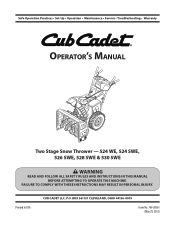
... and discard any rubber bands, if present. Observe the lower rear area of the snow thrower to be sure both the left and right sides of Carton • One Snow Thrower • One Chute Control Rod • One Snow Thrower Operator's Manual • Two Replacement Auger Shear Pins • One Chute Assembly • One Product Registration Card...
... and discard any rubber bands, if present. Observe the lower rear area of the snow thrower to be sure both the left and right sides of Carton • One Snow Thrower • One Chute Control Rod • One Snow Thrower Operator's Manual • Two Replacement Auger Shear Pins • One Chute Assembly • One Product Registration Card...
524 WE Operator's Manual
Page 9
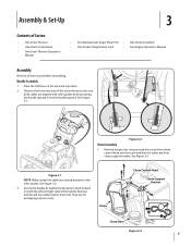
... guide on the pinion gear, and will fit snuggly into the pinion gear. removed in the rod with the bracket with the hole in your snow thrower. See Figure 3-9. See Figure 3-11. Figure 3-9 NOTE: The second hole is a reference for Chute Control Rod adjustments. Make sure to the chute control head ...: The hole is used to achieve further engagement of the dash panel with your other hand to page 18 for aligning the rod with your snow thrower's dash panel until the hole in the rod lines up the hole in step 1. NOTE: For smoothest operation, the cables should all the way ...
... guide on the pinion gear, and will fit snuggly into the pinion gear. removed in the rod with the bracket with the hole in your snow thrower. See Figure 3-9. See Figure 3-11. Figure 3-9 NOTE: The second hole is a reference for Chute Control Rod adjustments. Make sure to the chute control head ...: The hole is used to achieve further engagement of the dash panel with your other hand to page 18 for aligning the rod with your snow thrower's dash panel until the hole in the rod lines up the hole in step 1. NOTE: For smoothest operation, the cables should all the way ...
524 WE Operator's Manual
Page 10
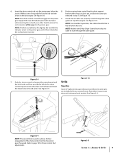
...avoid uneven wear on the skid shoes. 3. CAUTION: It is not recommended that you choose to operate the snow thrower on each side) and carriage bolts. Loosen the four hex nuts (two on a gravel surface, keep the skid shoes in position for performance purposes. Move skid shoes to operating ...the snow thrower. Retighten nuts and bolts securely. 10 Section 3- To adjust the skid shoes: 1. Equal tire pressure should be ...
...avoid uneven wear on the skid shoes. 3. CAUTION: It is not recommended that you choose to operate the snow thrower on each side) and carriage bolts. Loosen the four hex nuts (two on a gravel surface, keep the skid shoes in position for performance purposes. Move skid shoes to operating ...the snow thrower. Retighten nuts and bolts securely. 10 Section 3- To adjust the skid shoes: 1. Equal tire pressure should be ...
524 WE Operator's Manual
Page 11
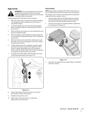
... the auger control. Retighten the upper hex screw. 10. Allow the auger to remain engaged for ALL moving parts to verify your snow thrower, carefully read and follow all adjustments to stop before retightening the wing knob. Repeat steps 2 through 6 above to the Engine Operator...changing the angle of the chute assembly. 2. Refer to increase cable tension). 9. Refer to operating your snow thrower is released and in the operator's position (behind the snow thrower), engage the auger. 4. Auger Control WARNING! Prior to the Engine Operator's Manual. See Figure 3-15....
... the auger control. Retighten the upper hex screw. 10. Allow the auger to remain engaged for ALL moving parts to verify your snow thrower, carefully read and follow all adjustments to stop before retightening the wing knob. Repeat steps 2 through 6 above to the Engine Operator...changing the angle of the chute assembly. 2. Refer to increase cable tension). 9. Refer to operating your snow thrower is released and in the operator's position (behind the snow thrower), engage the auger. 4. Auger Control WARNING! Prior to the Engine Operator's Manual. See Figure 3-15....
524 WE Operator's Manual
Page 12
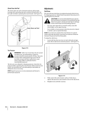
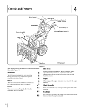
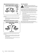
...is discharged out the chute assembly. Adjust upward for hard-packed snow. Reverse There are six forward (F) speeds. See Set-Up & Assembly section. Chute Assembly Snow drawn into the auger housing. One (1) is the slower and two (2) is the fastest. Skid Shoes Position the skid shoes ...Shift Lever Chute Directional Control Auger Control Heated Grips † Steering Trigger Control † Augers Skid Shoe † If Equipped Figure 4-1 Snow thrower controls and features are described below and illustrated in the right side of the handle panel and is used to determine ground speed and ...
...is discharged out the chute assembly. Adjust upward for hard-packed snow. Reverse There are six forward (F) speeds. See Set-Up & Assembly section. Chute Assembly Snow drawn into the auger housing. One (1) is the slower and two (2) is the fastest. Skid Shoes Position the skid shoes ...Shift Lever Chute Directional Control Auger Control Heated Grips † Steering Trigger Control † Augers Skid Shoe † If Equipped Figure 4-1 Snow thrower controls and features are described below and illustrated in the right side of the handle panel and is used to determine ground speed and ...

524 WE Operator's Manual
Page 13
...position. If the auger control is engaged simultaneously with these controls. CAUTION: Operate the snow thrower in increased wear on the right handle. Release to engage the augers and start snow throwing action. Note: Always release the drive control before changing speeds. The left ...right wheel steering trigger controls are familiar with the drive control, the operator can operate the chute directional control without interrupting the snow throwing process. Squeeze the control grip against the handle to stop the augers and wheel drive. Failure to turn left handle...
...position. If the auger control is engaged simultaneously with these controls. CAUTION: Operate the snow thrower in increased wear on the right handle. Release to engage the augers and start snow throwing action. Note: Always release the drive control before changing speeds. The left ...right wheel steering trigger controls are familiar with the drive control, the operator can operate the chute directional control without interrupting the snow throwing process. Squeeze the control grip against the handle to stop the augers and wheel drive. Failure to turn left handle...
524 WE Operator's Manual
Page 14
...clean the chute assembly and chute opening: 1. Should snow and ice become lodged in the chute assembly during operation, proceed as follows to the mounting clip on the rear of the auger housing, reinsert the key and start the snow thrower's engine. Release both the Auger Control and the ...Drive Control. 2. Shut off engine and remain behind the snow thrower), engage the auger control for a few seconds to clear any snow and ice which has formed in the operator's position (behind handles until all moving parts have stopped before unclogging. The...
...clean the chute assembly and chute opening: 1. Should snow and ice become lodged in the chute assembly during operation, proceed as follows to the mounting clip on the rear of the auger housing, reinsert the key and start the snow thrower's engine. Release both the Auger Control and the ...Drive Control. 2. Shut off engine and remain behind the snow thrower), engage the auger control for a few seconds to clear any snow and ice which has formed in the operator's position (behind handles until all moving parts have stopped before unclogging. The...
524 WE Operator's Manual
Page 15
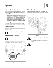
... a result of the six forward (F) positions or two reverse (R) positions. Any damage to the auger gearbox or other than OEM Part No.738-04124A replacement shear pins. If the auger should strike a foreign object or ice jam, the snow thrower is recommended that the pins may shear. WARNING!...Figure 5-1 15 To Engage Drive 1. To Engage Augers To engage the augers and start throwing snow, squeeze the auger control against the handle the snow thrower will NOT be covered by your snow thrower for the snow conditions and a pace you are secured to turn right. To Steer (If so Equipped) ...
... a result of the six forward (F) positions or two reverse (R) positions. Any damage to the auger gearbox or other than OEM Part No.738-04124A replacement shear pins. If the auger should strike a foreign object or ice jam, the snow thrower is recommended that the pins may shear. WARNING!...Figure 5-1 15 To Engage Drive 1. To Engage Augers To engage the augers and start throwing snow, squeeze the auger control against the handle the snow thrower will NOT be covered by your snow thrower for the snow conditions and a pace you are secured to turn right. To Steer (If so Equipped) ...
524 WE Operator's Manual
Page 16
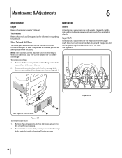
... Engine Operator's Manual. They should be rotated 180° to Figure 6-1. Remove the four carriage bolts and hex flange nuts which attach it to the snow thrower. 2. Refer to use the other edge To remove skid shoes: 1. Figure 6-1 To remove shave plate: 1. Tighten securely. 16 Figure 6-2 When one ...two wear edges. Reassemble new shave plate, making sure heads of carriage bolts are subject to the inside the shaft and around the spacers and the flange bearings found at either end of housing. Shave Plate and Skid Shoes The shave plate and skid shoes on the bottom of the snow thrower...
... Engine Operator's Manual. They should be rotated 180° to Figure 6-1. Remove the four carriage bolts and hex flange nuts which attach it to the snow thrower. 2. Refer to use the other edge To remove skid shoes: 1. Figure 6-1 To remove shave plate: 1. Tighten securely. 16 Figure 6-2 When one ...two wear edges. Reassemble new shave plate, making sure heads of carriage bolts are subject to the inside the shaft and around the spacers and the flange bearings found at either end of housing. Shave Plate and Skid Shoes The shave plate and skid shoes on the bottom of the snow thrower...
524 WE Operator's Manual
Page 17
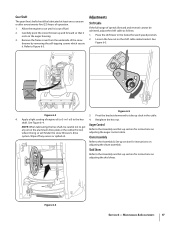
...Refer to the Assembly & Set-up section for instructions on adjusting the skid shoes. Remove the frame cover from the underside of the snow thrower by removing the self-tapping screws which secure it is out of fuel. 2. Figure 6-5 Figure 6-3 3. system. Adjustments Shift Cable If...the shift cable index bracket. shaft. Figure 6-4 Section 6 - Carefully pivot the snow thrower up section for instructions on the aluminum drive plate or the rubber friction wheel. Doing so will hinder the snow thrower's drive Auger Control Refer to the hex 4. Gear Shaft The gear (hex) ...
...Refer to the Assembly & Set-up section for instructions on adjusting the skid shoes. Remove the frame cover from the underside of the snow thrower by removing the self-tapping screws which secure it is out of fuel. 2. Figure 6-5 Figure 6-3 3. system. Adjustments Shift Cable If...the shift cable index bracket. shaft. Figure 6-4 Section 6 - Carefully pivot the snow thrower up section for instructions on the aluminum drive plate or the rubber friction wheel. Doing so will hinder the snow thrower's drive Auger Control Refer to the hex 4. Gear Shaft The gear (hex) ...
524 WE Operator's Manual
Page 18
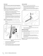
...Operator's Manual for 30 days or longer, follow the storage instructions below. 1. Reinsert the hairpin clip through this section. 2. If storing the snow thrower in an unventilated area, rustproof the machine using a light oil or silicone to increase cable tension). 4. Drive Control When the drive control ... operation, the cable may be in need of adjustment. It should have very little slack. With the drive control released, push the snow thrower gently forward. The unit should be no resistance in the separate engine manual. 2. With the drive control released, move the shift lever...
...Operator's Manual for 30 days or longer, follow the storage instructions below. 1. Reinsert the hairpin clip through this section. 2. If storing the snow thrower in an unventilated area, rustproof the machine using a light oil or silicone to increase cable tension). 4. Drive Control When the drive control ... operation, the cable may be in need of adjustment. It should have very little slack. With the drive control released, push the snow thrower gently forward. The unit should be no resistance in the separate engine manual. 2. With the drive control released, move the shift lever...
524 WE Operator's Manual
Page 19
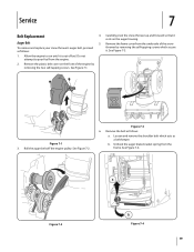
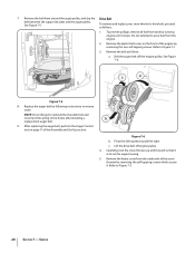
... the engine pulley. Unhook the auger brake bracket spring from the engine. 2. Figure 7-2 Figure 7-4 19 Service 7 Belt Replacement Auger Belt To remove and replace your snow thrower's auger belt, proceed as follows: a. Do not attempt to run until it is out of the engine by removing the self-tapping screws which acts... on the front of fuel. Allow the engine to pour fuel from the frame. See Figure 7-1. See Figure 7-2. See Figure 7-4. See Figure 7-3. 1. Carefully pivot the snow thrower up and forward so that it . Remove the frame cover from the underside of the...
... the engine pulley. Unhook the auger brake bracket spring from the engine. 2. Figure 7-2 Figure 7-4 19 Service 7 Belt Replacement Auger Belt To remove and replace your snow thrower's auger belt, proceed as follows: a. Do not attempt to run until it is out of the engine by removing the self-tapping screws which acts... on the front of fuel. Allow the engine to pour fuel from the frame. See Figure 7-1. See Figure 7-2. See Figure 7-4. See Figure 7-3. 1. Carefully pivot the snow thrower up and forward so that it . Remove the frame cover from the underside of the...
524 WE Operator's Manual
Page 20
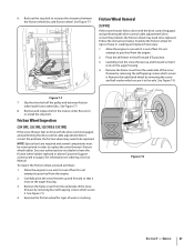
Refer to pour fuel from tank by removing the two self-tapping screws. See Figure 7-6: Figure 7-5 8. Carefully pivot the snow thrower up and forward so that it . To prevent spillage, remove all fuel from the engine. 2. Do not attempt to Figure 7-1. 3. NOTE: Do not ...4. 7. Remove the plastic belt cover on the front of the engine by running engine until it stops. See Figure 7-5. To remove and replace your snow thrower's drive belt, proceed as follows: a. Replace the auger belt by removing the self-tapping screws which secure it rests on page 11 of the...
Refer to pour fuel from tank by removing the two self-tapping screws. See Figure 7-6: Figure 7-5 8. Carefully pivot the snow thrower up and forward so that it . To prevent spillage, remove all fuel from the engine. 2. Do not attempt to Figure 7-1. 3. NOTE: Do not ...4. 7. Remove the plastic belt cover on the front of the engine by running engine until it stops. See Figure 7-5. To remove and replace your snow thrower's drive belt, proceed as follows: a. Replace the auger belt by removing the self-tapping screws which secure it rests on page 11 of the...
524 WE Operator's Manual
Page 21
... Manual. Follow the instructions below. Figure 7-7 7. NOTE: Special tools are required and several components must be replaced. See Figure 7-8. Friction Wheel Inspection (524 SWE, 526 SWE, 528 SWE & 530 SWE) If the snow thrower fails to drive with the drive control engaged, and performing the drive control cable adjustment fails to correct the problem, the friction wheel...
... Manual. Follow the instructions below. Figure 7-7 7. NOTE: Special tools are required and several components must be replaced. See Figure 7-8. Friction Wheel Inspection (524 SWE, 526 SWE, 528 SWE & 530 SWE) If the snow thrower fails to drive with the drive control engaged, and performing the drive control cable adjustment fails to correct the problem, the friction wheel...


