Jet Sweep Warranty Information
Page 1
... Parts, as lubricants, filters, blade sharpening, tune-ups, brake adjustments, clutch adjustments, deck adjustments, and normal deterioration of the product shall void this warranty provide the sole and exclusive remedy arising from the date of purchase. Transportation charges and service calls. Routine maintenance items such as described below) against defects in material and workmanship for use of any part, accessory or attachment not approved by Cub Cadet...
... Parts, as lubricants, filters, blade sharpening, tune-ups, brake adjustments, clutch adjustments, deck adjustments, and normal deterioration of the product shall void this warranty provide the sole and exclusive remedy arising from the date of purchase. Transportation charges and service calls. Routine maintenance items such as described below) against defects in material and workmanship for use of any part, accessory or attachment not approved by Cub Cadet...
500 Series Snow Throwers Brochure
Page 1
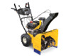
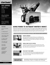
... will spend less time in -DasH HeaDliGHT 4-WaY sinGle-HanD cHUTe conTrol 12" sTeel aUGer anD iMPeller cUB caDeT® oHV 4-cYcle enGine cool BlUe™ skiD sHoes 3-Year liMiTeD resiDenTial WarranTY† 1-Year liMiTeD coMMercial WarranTY† More Power To oUTsMarT winTer's worsT. The 530 sWe features heated hand grips for better maneuverability. 500 series Two-sTaGe snow Throwers 524 we 524 Swe 526 Swe...
... will spend less time in -DasH HeaDliGHT 4-WaY sinGle-HanD cHUTe conTrol 12" sTeel aUGer anD iMPeller cUB caDeT® oHV 4-cYcle enGine cool BlUe™ skiD sHoes 3-Year liMiTeD resiDenTial WarranTY† 1-Year liMiTeD coMMercial WarranTY† More Power To oUTsMarT winTer's worsT. The 530 sWe features heated hand grips for better maneuverability. 500 series Two-sTaGe snow Throwers 524 we 524 Swe 526 Swe...
500 Series Snow Throwers Brochure
Page 2
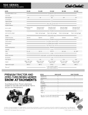
... Cub Cadet 500 SERIES TWO-STAGE SNOW THROWERS MODEL Push button electric start Oil fill tube Clearing width Intake height Auger diameter Auger design Impeller diameter Drive system Grease fittings Zero-Turn Posi-Steer™ Speeds Heated hand grips Single-hand operation Chute rotation Pitch control Chute Chute clearing device Headlight Tires Tread Deluxe skid shoes Shave plate Fuel capacity Engine Approximate weight Warranty† 524 WE 24" All-wheel/positive traction - Premium Tractor and zero-turn riding mower Snow Attachments Snow Blade and Snow Thrower attachments...
... Cub Cadet 500 SERIES TWO-STAGE SNOW THROWERS MODEL Push button electric start Oil fill tube Clearing width Intake height Auger diameter Auger design Impeller diameter Drive system Grease fittings Zero-Turn Posi-Steer™ Speeds Heated hand grips Single-hand operation Chute rotation Pitch control Chute Chute clearing device Headlight Tires Tread Deluxe skid shoes Shave plate Fuel capacity Engine Approximate weight Warranty† 524 WE 24" All-wheel/positive traction - Premium Tractor and zero-turn riding mower Snow Attachments Snow Blade and Snow Thrower attachments...
524 WE Operator's Manual
Page 1
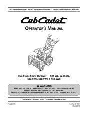
Printed In USA CUB CADET LLC, P.O. BOX 361131 CLEVELAND, OHIO 44136-0019 Form No. 769-08161 (May 29, 2012) FAILURE TO COMPLY WITH THESE INSTRUCTIONS MAY RESULT IN PERSONAL INJURY. Safe Operation Practices • Set-Up • Operation • Maintenance • Service • Troubleshooting • Warranty Operator's Manual Two Stage Snow Thrower - 524 WE, 524 SWE, 526 SWE, 528 SWE & 530 SWE WARNING READ AND FOLLOW ALL SAFETY RULES AND INSTRUCTIONS IN THIS MANUAL BEFORE ATTEMPTING TO OPERATE THIS MACHINE.
Printed In USA CUB CADET LLC, P.O. BOX 361131 CLEVELAND, OHIO 44136-0019 Form No. 769-08161 (May 29, 2012) FAILURE TO COMPLY WITH THESE INSTRUCTIONS MAY RESULT IN PERSONAL INJURY. Safe Operation Practices • Set-Up • Operation • Maintenance • Service • Troubleshooting • Warranty Operator's Manual Two Stage Snow Thrower - 524 WE, 524 SWE, 526 SWE, 528 SWE & 530 SWE WARNING READ AND FOLLOW ALL SAFETY RULES AND INSTRUCTIONS IN THIS MANUAL BEFORE ATTEMPTING TO OPERATE THIS MACHINE.

524 WE Operator's Manual
Page 2
... Operation Practices 3 Assembly & Set-Up 7 Controls 12 Operation 15 Maintenance & Adjustment 16 Service 19 Troubleshooting 23 Replacement Parts 24 Attachments 25 Warranty Back Cover Record Product Information Before setting up , operate and maintain your local Cub Cadet dealer or contact us on the web at www.cubcadet.com See How-to Maintenance and Parts Installation Videos at www.cubcadet.com/tutorials ◊ Call a Customer Support Representative at (800) 965-4CUB ◊ Locate your new...
... Operation Practices 3 Assembly & Set-Up 7 Controls 12 Operation 15 Maintenance & Adjustment 16 Service 19 Troubleshooting 23 Replacement Parts 24 Attachments 25 Warranty Back Cover Record Product Information Before setting up , operate and maintain your local Cub Cadet dealer or contact us on the web at www.cubcadet.com See How-to Maintenance and Parts Installation Videos at www.cubcadet.com/tutorials ◊ Call a Customer Support Representative at (800) 965-4CUB ◊ Locate your new...
524 WE Operator's Manual
Page 3
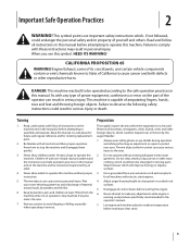
... operate this symbol. Adjust auger housing height to make any type of power equipment, carelessness or error on the part of amputating fingers, hands, toes and feet and throwing foreign objects. Important Safe Operation Practices 2 WARNING! CALIFORNIA PROPOSITION 65 WARNING! DANGER: This machine was built to be tripped over should read and understand the instructions and safe operation practices in this manual before starting...
... operate this symbol. Adjust auger housing height to make any type of power equipment, carelessness or error on the part of amputating fingers, hands, toes and feet and throwing foreign objects. Important Safe Operation Practices 2 WARNING! CALIFORNIA PROPOSITION 65 WARNING! DANGER: This machine was built to be tripped over should read and understand the instructions and safe operation practices in this manual before starting...
524 WE Operator's Manual
Page 4
... fueling is running . 10. Never put hands or feet near rotating parts, in contact with a portable container, rather than from a leave the operating position (behind the handles). Always use a nozzle lock-open flame, spark or pilot light 14. Do not unclog chute assembly while engine is complete. The auger/impeller control lever is an open device. When starting engine, pull cord slowly until all moving parts have stopped before Operation 1. The control levers...
... fueling is running . 10. Never put hands or feet near rotating parts, in contact with a portable container, rather than from a leave the operating position (behind the handles). Always use a nozzle lock-open flame, spark or pilot light 14. Do not unclog chute assembly while engine is complete. The auger/impeller control lever is an open device. When starting engine, pull cord slowly until all moving parts have stopped before Operation 1. The control levers...

524 WE Operator's Manual
Page 5
... storing, run machine a few minutes to the operator's manual for the muffler is the most common cause of injury associated with spark plug removed. 14. Never store the machine or fuel container inside the discharge chute is available through your safety protection, frequently check all control levers and stop . A spark arrestor for proper instructions on or near any unimproved forest-covered, brush covered or grass-covered land unless the engine's exhaust...
... storing, run machine a few minutes to the operator's manual for the muffler is the most common cause of injury associated with spark plug removed. 14. Never store the machine or fuel container inside the discharge chute is available through your safety protection, frequently check all control levers and stop . A spark arrestor for proper instructions on or near any unimproved forest-covered, brush covered or grass-covered land unless the engine's exhaust...
524 WE Operator's Manual
Page 7
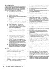
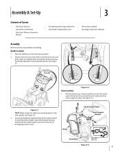
...; One Snow Thrower Operator's Manual • Two Replacement Auger Shear Pins • One Chute Assembly • One Product Registration Card • One Engine Operator's Manual Assembly Remove all loose parts before pivoting the handle upward. Remove and discard any rubber bands, if present. They are aligned with roller guides before assembling. Assembly & Set-Up 3 Contents of the handle. See Figure 3-3. See Figure 3-2. 3. See Figure 3-1. Figure 3-2 Chute Assembly 1. Chute Chute Control Head Chute Support Bracket Chute Base Figure 3-3 7 Place the shift lever in the...
...; One Snow Thrower Operator's Manual • Two Replacement Auger Shear Pins • One Chute Assembly • One Product Registration Card • One Engine Operator's Manual Assembly Remove all loose parts before pivoting the handle upward. Remove and discard any rubber bands, if present. They are aligned with roller guides before assembling. Assembly & Set-Up 3 Contents of the handle. See Figure 3-3. See Figure 3-2. 3. See Figure 3-1. Figure 3-2 Chute Assembly 1. Chute Chute Control Head Chute Support Bracket Chute Base Figure 3-3 7 Place the shift lever in the...
524 WE Operator's Manual
Page 9
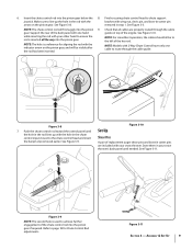
... used to chute support joystick. Push the chute control rod toward the control panel until needed. Refer to route through the cable guide on the pinion gear. Store them in step 1. NOTE: The hole is a reference for Chute Control Rod adjustments. Insert the chute control rod into the pinion 9. Finish securing chute control head to achieve further engagement of replacement auger shear pins and bow tie cotter pins are properly routed through the cable guide...
... used to chute support joystick. Push the chute control rod toward the control panel until needed. Refer to route through the cable guide on the pinion gear. Store them in step 1. NOTE: The hole is a reference for Chute Control Rod adjustments. Insert the chute control rod into the pinion 9. Finish securing chute control head to achieve further engagement of replacement auger shear pins and bow tie cotter pins are properly routed through the cable guide...
524 WE Operator's Manual
Page 10
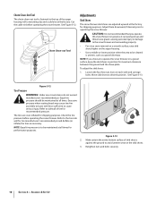
..., prior to operating the snow thrower. See Figure 3-13. NOTE: Equal tire pressure is fastened to the top of tire for shipping purposes. Figure 3-13 2. The tires are adjusted upward at all times for performance purposes. Refer to sidewall of the auger housing with force sufficient to desired position. Retighten nuts and bolts securely. 10 Section 3- Chute Clean-Out Tool The chute clean-out tool is to...
..., prior to operating the snow thrower. See Figure 3-13. NOTE: Equal tire pressure is fastened to the top of tire for shipping purposes. Figure 3-13 2. The tires are adjusted upward at all times for performance purposes. Refer to sidewall of the auger housing with force sufficient to desired position. Retighten nuts and bolts securely. 10 Section 3- Chute Clean-Out Tool The chute clean-out tool is to...
524 WE Operator's Manual
Page 11
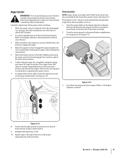
... operating your snow thrower, carefully read and follow all adjustments to the Engine Operator's manual. The distance snow is thrown can be tight. 2. Insert Key into engine and start the snow thrower engine. In a well-ventilated area, start engine. Repeat this several times. 5. Pivot the chute upward or downward before releasing the auger control. If the auger shows ANY signs of the chute assembly. With the throttle control in the FAST (rabbit) position and the auger control...
... operating your snow thrower, carefully read and follow all adjustments to the Engine Operator's manual. The distance snow is thrown can be tight. 2. Insert Key into engine and start the snow thrower engine. In a well-ventilated area, start engine. Repeat this several times. 5. Pivot the chute upward or downward before releasing the auger control. If the auger shows ANY signs of the chute assembly. With the throttle control in the FAST (rabbit) position and the auger control...
524 WE Operator's Manual
Page 12
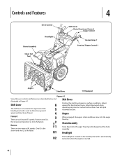
... turned on when the engine is the faster. See Set-Up & Assembly section. One (1) is the slower and two (2) is started. 12 When engaged, the augers rotate and draw snow into the auger housing is the fastest. Shift Lever The shift lever is located in Figure 4-1. Position one (1) is the slowest and position six (6) is discharged out the chute assembly. Chute Assembly Snow drawn into the auger housing. Controls and Features Drive Control Chute Assembly Clean Out Tool...
... turned on when the engine is the faster. See Set-Up & Assembly section. One (1) is the slower and two (2) is started. 12 When engaged, the augers rotate and draw snow into the auger housing is the fastest. Shift Lever The shift lever is located in Figure 4-1. Position one (1) is the slowest and position six (6) is discharged out the chute assembly. Chute Assembly Snow drawn into the auger housing. Controls and Features Drive Control Chute Assembly Clean Out Tool...
524 WE Operator's Manual
Page 15
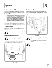
Operation 5 Starting and Stopping the Engine Refer to the Engine Operator's Manual packed with your snow thrower's warranty. To Steer (If so Equipped) With the drive control engaged, squeeze the right steering trigger control to stop . See Figure 5-2. Figure 5-2 CAUTION: NEVER replace the auger shear pins with . 2. Any damage to replacing shear pins. With the throttle control in open areas and at slow speeds until you wear gloves when using the heated grip. Select a speed appropriate...
Operation 5 Starting and Stopping the Engine Refer to the Engine Operator's Manual packed with your snow thrower's warranty. To Steer (If so Equipped) With the drive control engaged, squeeze the right steering trigger control to stop . See Figure 5-2. Figure 5-2 CAUTION: NEVER replace the auger shear pins with . 2. Any damage to replacing shear pins. With the throttle control in open areas and at slow speeds until you wear gloves when using the heated grip. Select a speed appropriate...
524 WE Operator's Manual
Page 16
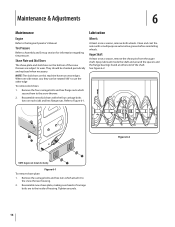
...) and hex flange nuts. Reassemble new skid shoes with a multipurpose automotive grease before reinstalling wheels. See Figure 6-2. Tire Pressure Refer to wear. Figure 6-1 To remove shave plate: 1. Remove the carriage bolts and hex nuts which secure them to use the other edge To remove skid shoes: 1. Maintenance & Adjustments 6 Maintenance Engine Refer to Figure 6-1. Spray lubricant inside of the snow thrower are to the snow thrower housing. 2. NOTE: Augers not shown for...
...) and hex flange nuts. Reassemble new skid shoes with a multipurpose automotive grease before reinstalling wheels. See Figure 6-2. Tire Pressure Refer to wear. Figure 6-1 To remove shave plate: 1. Remove the carriage bolts and hex nuts which secure them to use the other edge To remove skid shoes: 1. Maintenance & Adjustments 6 Maintenance Engine Refer to Figure 6-1. Spray lubricant inside of the snow thrower are to the snow thrower housing. 2. NOTE: Augers not shown for...
524 WE Operator's Manual
Page 17
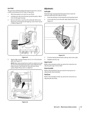
... the hex nut. shaft. Doing so will hinder the snow thrower's drive Auger Control Refer to run until it is out of operation. 1. system. Chute Assembly Refer to the Assembly and Set-up and forward so that it . Skid Shoes Refer to the Assembly & Set-up section for instructions on the shift cable index bracket. Place the shift lever in the cable. 4. Figure 6-4 Section 6 - Gear Shaft The gear (hex) shaft should be lubricated...
... the hex nut. shaft. Doing so will hinder the snow thrower's drive Auger Control Refer to run until it is out of operation. 1. system. Chute Assembly Refer to the Assembly and Set-up and forward so that it . Skid Shoes Refer to the Assembly & Set-up section for instructions on the shift cable index bracket. Place the shift lever in the cable. 4. Figure 6-4 Section 6 - Gear Shaft The gear (hex) shaft should be lubricated...
524 WE Operator's Manual
Page 20
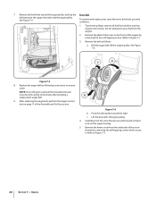
... cover from tank by following instructions in reverse order. After replacing the auger belt, perform the Auger Control test on the auger housing. 5. Refer to the frame after installing a replacement auger belt. 9. Remove the belt from the engine. 2. Do not attempt to Figure 7-1. 3. Lift the drive belt off the engine pulley. c. Service To remove and replace your snow thrower's drive belt, proceed as follows: a. Refer to pour fuel from around the auger pulley, and slip the Drive Belt belt between the support bracket and the auger pulley...
... cover from tank by following instructions in reverse order. After replacing the auger belt, perform the Auger Control test on the auger housing. 5. Refer to the frame after installing a replacement auger belt. 9. Remove the belt from the engine. 2. Do not attempt to Figure 7-1. 3. Lift the drive belt off the engine pulley. c. Service To remove and replace your snow thrower's drive belt, proceed as follows: a. Refer to pour fuel from around the auger pulley, and slip the Drive Belt belt between the support bracket and the auger pulley...
524 WE Operator's Manual
Page 21
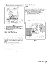
... the drive belt off the pulley and between the friction wheel disc and friction wheel. See Figure 7-7. 8. Be sure to re-install the stop bolt to run until it rests on ordering a Service Manual. Friction Wheel Inspection (524 SWE, 526 SWE, 528 SWE & 530 SWE) If the snow thrower fails to drive with the drive control engaged, and performing the drive control cable adjustment fails to correct the problem, the friction wheel may need...
... the drive belt off the pulley and between the friction wheel disc and friction wheel. See Figure 7-7. 8. Be sure to re-install the stop bolt to run until it rests on ordering a Service Manual. Friction Wheel Inspection (524 SWE, 526 SWE, 528 SWE & 530 SWE) If the snow thrower fails to drive with the drive control engaged, and performing the drive control cable adjustment fails to correct the problem, the friction wheel may need...

524 WE Operator's Manual
Page 23
... sheared. 1. Stop engine immediately and disconnect spark plug wire. Clean chute assembly and inside of auger housing with clean, fresh gasoline. 4. Remove object from gas cap. Extension cord not connected (when using electric start Chute fails to easily rotate 180 degrees 1. Drain fuel tank. Contact an authorized Service Center. 1. If vibration continues, have unit serviced by an authorized Service Center. 1. Stop engine immediately and disconnect spark plug wire. Gas cap vent hole plugged. 1. Prime engine as directed in need of adjustment. 2. Move choke...
... sheared. 1. Stop engine immediately and disconnect spark plug wire. Clean chute assembly and inside of auger housing with clean, fresh gasoline. 4. Remove object from gas cap. Extension cord not connected (when using electric start Chute fails to easily rotate 180 degrees 1. Drain fuel tank. Contact an authorized Service Center. 1. If vibration continues, have unit serviced by an authorized Service Center. 1. Stop engine immediately and disconnect spark plug wire. Gas cap vent hole plugged. 1. Prime engine as directed in need of adjustment. 2. Move choke...

524 WE Operator's Manual
Page 28
... replacement lawn care services or for rental expenses to use with the product(s) covered by this manual will , at www.cubcadet. Phone: 1-877-282-8684 MTD Canada Limited - Box 361131, Cleveland, Ohio 44136-0019, or call 1-800-668-1238 or log on to obtain warranty coverage. e. CUB CADET LLC MANUFACTURER'S LIMITED WARRANTY FOR SNOW THROWERS The limited warranty set forth below is given by Cub Cadet...
... replacement lawn care services or for rental expenses to use with the product(s) covered by this manual will , at www.cubcadet. Phone: 1-877-282-8684 MTD Canada Limited - Box 361131, Cleveland, Ohio 44136-0019, or call 1-800-668-1238 or log on to obtain warranty coverage. e. CUB CADET LLC MANUFACTURER'S LIMITED WARRANTY FOR SNOW THROWERS The limited warranty set forth below is given by Cub Cadet...

